Transcription of Design and the mechanism of controlling a robotic arm
1 I Syrian Private University Faculty of Computer & Informatics Engineering Design and the mechanism of controlling a robotic arm A Senior Project Presented to the Faculty of Computer and Informatics Engineering In Partial Fulfillment of the Requirements for the Degree Of Bachelor of in Communication & Network Engineering Under the supervision of Prof. Ahmad Rateb Al-Najjar Prof. Ali Skaff II By Noor Ali Al teef Yousef Sofyan Jghef Hasan Mohamed Heddeh Mohamed Zaki Hani Ibrahim Mohammed Ali Ismail Abdul Rahman August 2015 2015 - ALL RIGHTS RESERVED CERTIFICATION OF APPROVAL III Prof. Ahmad Rateb Al-Najjar Date : ---------------------------------------- ------------------------ ------------------------------------- Prof. Ali Skaff Date : ---------------------------------------- ------------------------ ------------------------------------ IV CONTENT Table of Figure.
2 VI CHAPTER 1: INTRODUCTION .. 2 CHAPTER 2: DESIGNING PORTION .. 3 Design Of robotic Arm .. 3 Five degrees of freedom .. 4 Positive and negative on robotic arm .. 5 The Positive : .. 5 The negative : .. 6 CHAPTER 3: THEORETICAL PORTION .. 7 7 Specifications .. 8 Programming .. 9 Power .. 9 Memory .. 10 Arduino development "IDE" .. 11 CHAPTER 4: PRACTICAL PORTION .. 13 servo Motors .. 13 Theory of DC servo Motor .. 15 Separately Excited DC servo Motor .. 15 DC servo Motor Theory : .. 15 Field Controlled DC servo Motor Theory .. 16 Armature Controlled DC servo Motor Theory: .. 18 Permanent Magnet DC servo Motor : .. 19 Deriving State Equations for a DC servo Motor .. 19 V Model : .. 19 Developing The State Equations : .. 20 Potentiometers .. 22 Bluetooth HC-06 module .. 23 Specifications .. 24 Hardware features.
3 24 Software features .. 24 CHAPTER 5: MECHANICAL PORTION .. 28 Design .. 29 Driving engines using complementary angle .. 34 Robot Arm 34 End-Effector Selection .. 35 MIT App Inventor .. 36 robotic arm app using MIT app inventor .. 37 Interface designer : .. 39 Interface Blocks: .. 40 App Designer: .. 40 Arm Block Diagram: .. 41 CONCLUSION .. 43 REFERENCE .. 44 Appendix A .. 46 VI Table of Figure shows the image of a servo motor 4 Five degrees of freedom 4 Robot Arm 5 Arduino Uno microcontroller board (interface) 7 Figure Arduino Uno microcontroller board(back view) 8 Figure Arduino Power Supply 10 Figure ATmega328P Memory 10 Figure Interface Arduino Uno Program 11 Figure Big servo Motor 13 Figure G9 servo Motor 14 Figure Block diagram of a servo motor 14 Figure Separately Excited DC servo Motor 15 Figure Field controlled DC servo motor 16 Figure knee point of magnetizing saturation curve
4 17 Figure knee point of magnetizing saturation 18 Figure The terms Ra and La are the resistance 20 Figure Simulation Diagram For The DC servo Motor 21 Figure A Potentiometer 22 Figure Circuit Diagram of a Potentiometer 23 Figure Bluetooth module (Front View) 24 Figure Bluetooth module(Back View) 24 VII Figure Free body diagram of the robot arm 26 Figure Work region of the robotic arm 27 Figure Force diagram of robot arm 27 Figure Force diagram of link CB 28 Figure Two Type Of servo Motor 30 Figure Electronic scheme of control 32 Figure gripper Closed.
5 Gripper Open 33 Figure MIB Structure 34 Interface designer 36 Interface Blocks 37 Figure App Designer 38 Figure Arm Block Diagram 39 1 ATMEGA-328p Arduino 2 CHAPTER 1: INTRODUCTION A Robot is a virtually intelligent agent capable of carrying out tasks robotically with the help of some supervision.
6 Practically, a robot is basically an electro-mechanical machine that is guided by means of computer and electronic programming. Robots can be classified as autonomous, semiautonomous and remotely controlled. Robots are widely used for variety of tasks such as service stations, cleaning drains, and in tasks that are considered too dangerous to be performed by humans. A robotic arm is a robotic manipulator, usually programmable, with similar functions to a human arm. This robotic arm is programmable in nature and it can be manipulated. The robotic arm is also sometimes referred to as anthropomorphic as it is very similar to that of a human hand. Humans today do all the tasks involved in the manufacturing industry by themselves. However, a robotic arm can be used for various tasks such as welding, drilling, spraying and many more.
7 A self-sufficient robotic arm is fabricated by using components like micro -controllers and motors. This increases their speed of operation and reduces the complexity. It also brings about an increase in productivity which makes it easy to shift to hazardous materials. The main part of the Design is ATMEGA-328p micro -controller which coordinates and controls the product s action. This specific micro controller is used in various types of embedded applications. Robotics involves elements of mechanical and electrical engineering, as well as control theory, computing and now artificial intelligence. According to the Robot Institute of America, A robot is a reprogrammable, multifunctional manipulator designed to move materials, parts, tools or specialized devices through variable programmed motions for the performance of a variety of tasks.
8 The robots interact with their environment, which is an important objective in the development of robots. This interaction is commonly established by means of some sort of arm and gripping device or end effectors. In the robotic arm, the arm has a few joints, similar to a human arm, in addition to shoulder, elbow, and wrist, coupled with the finger 3 joints; there are many joints . The Design process is clearly explained in the next section with detailed information regarding the components which are used. CHAPTER 2: DESIGNING PORTION Design of robotic Arm The robotic Arm is designed using the Microcontroller ATMEGA328p micro -controller using Arduino programming. This process works on the principle of interfacing servos and potentiometers. This task is achieved by using Arduino board. Potentiometers play an important role The remote is fitted with potentiometers and the servos are attached to the body of the robotic arm.
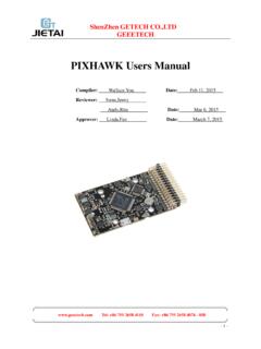
9 The potentiometer converts the mechanical motion into electrical motion. Hence, on the motion of the remote the potentiometers produce the electrical pulses, which are in route for the Arduino board. The board then processes the signals received from the potentiometers and finally, converts them into requisite digital pulses that are then sent to the servomotors. This servo will respond with regards to the pulses which results in the moment of the arm. Figure shows the image of a servo motor. It consists of a motor which is coupled to a sensor, used for position feedback, through a reduction gearbox. It also accompanies a relatively sophisticated controller, usually a dedicated module designed specifically for use with servo motors In short, the micro controller interfaces all these components specified below.
10 A short list of components include 1. servo motors 2. Potentiometers 3. Atmega 328p. 4. Arduino Deumilanove "IDE" 5. Bloutooth module. 4 shows the image of a servo motor Five degrees of freedom Serial and parallel manipulator systems are generally designed to position an end-effector with five degrees of freedom, consisting of three in translation and tow in orientation. This provides a direct relationship between actuator positions and the configuration of the manipulator Five degrees of freedom 5 Robot arms are described by their degrees of freedom. This number typically refers to the number of single-axis rotational joints in the arm, where higher number indicates an increased flexibility in positioning a tool. This is a practical metric, in contrast to the abstract definition of degrees of freedom which measures the aggregate positioning capability of a system.