Transcription of Design Example 1 Reinforced Concrete Wall - iccsafe.org
1 2012 IBC SEAOC Structural/Seismic Design Manual, Vol. 3 1 Design Example 1 Reinforced Concrete WallOVERVIEWThe structure in this Design Example is an eight-story offi ce with load-bearing Reinforced Concrete walls as its seismic-force-resisting system. This Design Example focuses on the Design and detailing of one of the 30-foot, 6-inch-long walls running in the transverse building purpose of this Design Example is twofold:1. To demonstrate the Design of a solid Reinforced Concrete wall for fl exure and shear, including bar cut-offs and lap To demonstrate the Design and detailing of wall boundary Design Example assumes that Design lateral forces have already been determined for the structure and that the forces have been distributed to the walls of the structure by a hand or computer analysis.
2 This analysis has provided the lateral displacements corresponding to the Design lateral 18/6/13 3:36 PM8/6/13 3:36 PM2 2012 IBC SEAOC Structural/Seismic Design Manual, Vol. 3 Design Example 1 Reinforced Concrete WallOUTLINE1. Building Geometry and Loads2. Load Combinations for Design3. Preliminary Sizing of Wall4. Flexural Strength at Base of Wall5. Flexural Strength and Lap Splices over Height of Wall6. Shear Strength of Wall7. Shear Friction (Sliding Shear) Strength of Wall8. Detailing of Wall Boundary Elements1. Building Geometry and Loads ASCE GIVEN INFORMATIONThis Design Example follows the general building code requirements of the 2012 International Building Code (2012 IBC) and ASCE 7.
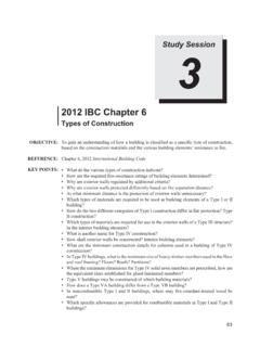
3 For structural Concrete Design , the 2012 IBC references the American Concrete Institute Building Code (ACI 318) as indicated in Section This Example follows the requirements of ACI 318-11. Discussions related to the SEAOC Blue Book recommendations refer to the document Recommended Lateral Force Recommendations and Commentary (SEAOC, 1999) as well as the Blue Book online articles on specifi c topics (SEAOC, 2009) as 1 1 shows the typical fl oor plan of the structure. The Design and analysis of the structure is based on a response modifi cation coeffi cient, R, of 5 (ASCE 7 Table 1) for a bearing wall system with special Reinforced Concrete shear walls.
4 The defl ection amplifi cation factor, Cd, is 5. The SEAOC Blue Book (2009, Article ) expresses the opinion that the R value for Concrete bearing-wall systems (R = 5) and that for walls in building frame systems (R = 6) should be the same, which may be justifi ed based on detailing provisions. To be consistent with the current code requirements though, this Design Example uses R = spectral response acceleration values from ASCE 7 maps (Figures 22 1 through 22 11) are S1 = SS = Site Class D Risk Category 28/6/13 3:36 PM8/6/13 3:36 PM2012 IBC SEAOC Structural/Seismic Design Manual, Vol.
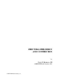
5 3 3 Design Example 1 Reinforced Concrete Wall Seismic Design Category D Redundancy factor, = Seismic Importance factor, I = Concrete strength, fcff = 5000 psi Steel yield strength, fy = 60 ksiFigure 1 1. Floor Design LOADS AND LATERAL FORCESF igure 1 2 shows the wall elevation and shear and moment diagrams. The wall carries axial forces PD (resulting from dead load including self-weight of the wall) and PL (resulting from live load) as shown in Table 1 1. Live loads have already been reduced according to IBC Section The shear, VE, and moment , ME, resulting from the Design lateral earthquake forces are also shown in Table 1 1.
6 The forces are from a linear static 38/6/13 3:36 PM8/6/13 3:36 PM4 2012 IBC SEAOC Structural/Seismic Design Manual, Vol. 3 Design Example 1 Reinforced Concrete WallFigure 1 2. Wall elevation, shear, and moment diagramTable 1 1. Design loads and lateral forcesLevelPD (kips)PL (kips)VE (kips)ME (kip-ft)Roof1933784083887224492875731084 14363067581445958210594518178514,8004113 021798723,50031310253122034,400215402901 42048,000173, 48/6/13 3:36 PM8/6/13 3:36 PM2012 IBC SEAOC Structural/Seismic Design Manual, Vol. 3 5 Design Example 1 Reinforced Concrete WallFor this Design Example , it is assumed that the foundation system is rigid, and thus the wall is considered to have a fi xed base.
7 The fi xed-base assumption is made here primarily to simplify the Example . In an actual structure, the effect of foundation fl exibility and its consequences on structural deformations should be analysis uses effective section properties for the stiffness of Concrete elements. Example 2 includes a discussion of effective section properties for use in the fi xed-base assumption and effective section properties, the horizontal displacement at the top of the wall corresponding to the Design lateral forces is inches. This displacement is needed for the detailing of boundary zones according to ACI 318 Section , which is illustrated in Part 8 of this Design Load Combinations for Design ASCE LOAD COMBINATIONSLoad combinations for the seismic Design of Concrete are given in Section (This is indicated in Section )
8 Equations 5 and 7 of Section are the seismic Design load combinations to be used for + + L + + combinations for non-seismic loads for Reinforced Concrete are given in Section , Equations 1, 2, 3, 4, and HORIZONTAL AND VERTICAL COMPONENTS OF EARTHQUAKE FORCEThe term E in the load combinations includes horizontal and vertical components according to Equations 1 and 2 of Section :E = Eh + Ev Eq 1E = Eh Ev Eq 2where Eh and Ev are defi ned according to Equations 3 and
9 4 of Section and Section as follows:Eh = QE Eq 3Ev = Eq 4 Substituting this into the seismic-load combinations results in( + )D + QE + L + ( )D + 58/6/13 3:36 PM8/6/13 3:36 PM