Transcription of Design Guide MD#1R2 - USDA
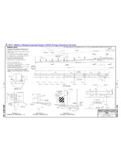
1 Design Guide MD #1 Roof gutter Design Method CONSTRUCTION DETAILS AND SPECIFICATIONS Maryland Revised October 2004 Design Guide MD#1 Roof gutter Design Method NRCS Engineering, Maryland October 2004 Page i TABLE OF CONTENTS SECTION PAGES I General Information 1 II Construction Specifications and Worksheets Design Data 2 Construction Check Data 3 Roof gutter Design Instructions 4 Worksheet 1 (Roof gutter Design Sheet) 5 Worksheet 2 (Underground Outlet Design Sheet) 6 Chart 1 (5 Minute Rainfall Intensities) 7 Figure 1 (Galvanized K-Style gutter ) 8 Figure 2 (Aluminum K-Style gutter ) 9 Figure 3 (Schedule 40 Half-Round) 10 Figure 4 (Downspout Outlet Sizing) 11 Figure 5 (Corrugated Underground Outlet Drain Chart) 12 Figure 6 (Smooth Underground Outlet Drain Chart) 13 Figure 7 (Fascia Boards Replacement Flow Chart) 14 III Construction Specifications 15 IV Construction Drawings 16-21 Details: 558-A Detail of leader pipe and downspout with underground outlet 17 558-B Detail of leader pipe and downspout with splash pad 18 558-C 6 half round PVC gutter hanger 19 558-D 6 half round PVC gutter 20 558-E 8 half round PVC gutter 21 558-F 8 half round PVC gutter hanger 22 V Sizing Example 23-25 Worksheet 1 24 Worksheet 2 Underground Outlet sizing 25 Design Guide MD#1 Roof gutter Design Method NRCS Engineering, Maryland October 2004 Page 1 SECTION I GENERAL This Design Guide is a technical resource prepared by the Maryland NRCS Engineering staff and is intended for use by the NRCS in Maryland and its partners.
2 Construction drawings for some of the gutter options are included, as well as other appropriate construction details and specifications. To aid in the Design process, some drawings and specifications are available online at the Maryland NRCS website at No changes are allowed on these details without prior approval from the NRCS engineering staff. There are many different manufactures of roof gutter and related materials. The flows and capacities of the roof gutter and downspouts shown in this Design Guide are based on actual measurements taken from some of the materials available. For practical purposes the roof gutter depths and areas used are assumed to hold true for all available gutter of a given style, top width and material even though differences do occur. It is the judgement of the engineering staff that these differences are minor and are neglected in the development of this Design Guide .
3 The capacities of downspout outlets are based on using the manufacturers preformed (insert) outlets. Not all sizes of downspouts will fit on a given size of roof gutter . Typically, a 5-inch top width K-style gutter can receive a 2 x 3 downspout. A 3 x 4 downspout can also fit. Some trimming of the flange on the preformed outlet may be required. A 6-inch top width K-style gutter can receive a 3 x 4 downspout. A 4 x 5 downspout can also fit, but again some trimming of the flange of the preformed downspout outlet may be required. The above sizing is reflected in the development of Figure 4 (Downspout Outlet Sizing, Leader Pipe Sizing). The use of 4 x 5 downspout outlets starts at a depth of gutter of inches. This corresponds to a minimum top width of 6 inches. The availability of 7-inch top width K-style gutter has been poor in the past.
4 However, in recent years some seamless forms of 7-inch gutter as well as other sizes have become available. Sizes larger than 7 inches have also been developed. Check for local availability before specifying sizes 7 inches or larger. In section II, Construction Check Data are contractor certification statements. Contractor certification is highly encouraged. Many roof runoff systems are constructed on buildings requiring a ladder or hydraulic lift in order to properly inspect the work being completed. In addition, the type of hangers used and materials available is constantly changing. In lieu of climbing ladders and using the hydraulic lifts to inspect the installed work, the contractor certifications are recommended. The use of snow guards is not mentioned and their use is neither encouraged nor discouraged.
5 Some of the buildings in which roof gutters are being installed are over a century old. Even though the condition of these buildings may be good, we feel it inappropriate to add any loading to the roofs. The decision for the use of snow guards is that of the landowners. Rafters and fascia boards must be in good conditions in order to properly hang and support the roof gutter . It is common for rafter ends to be damaged and fascia boards to be missing or damaged. Rafter ends must be repaired and fascia boards replaced as needed. When roofs are in poor conditions repairs should be made by the landowner before any recommendations to install roof gutter are made. There may be situations when a roof is in a poor or unsafe condition and alternatives other than roof runoff structure will be required.
6 See Figure 7 for a flow chart in determining fascia board replacement. Design Guide MD#1 Roof gutter Design Method NRCS Engineering, Maryland October 2004 Page 2 In section IV of the Design Guide is a sample Design , which includes Design calculations and plan sketch. SECTION II Design DATA Record on appropriate engineering paper. The following is a list of the minimum required Design data: 1. Determine roofs, which need roof runoff structure and where the systems may safely outlet. 2. Determine peak runoff from each roof for the Design storm selected. 3. Select type of gutter to be used. 4. Size gutter based on type, peak flow and slope. (See Figures 1,2 and 3). 5. Determine the downspout outlets required for each roof to be guttered, and choose a downspout system. (See Figure 4). 6. Drawings shall include the following as a minimum: Plan view; gutter location, gage, type, size, direction, slope, fascia board and rafter end replacement or repair, and mounting instructions, underground outlet type, size, direction and installation instructions, and construction specifications.
7 Design Guide MD#1 Roof gutter Design Method NRCS Engineering, Maryland October 2004 Page 3 CONSTRUCTION CHECK DATA Record on appropriate engineering paper. The following is a list of the minimum required construction check data: 1. Documentation of site visits on CPA-6. The documentation shall include the date, who performed the inspection, specifics as to what was inspected, all alternatives discussed, and decisions made and by whom. 2. Contractor certification certifying the roof gutter and downspout type, sizes, gage, roof gutter slope and mounting method. If rafter ends or fascia boards are repaired or replaced, the certification shall also include the rafter end and fascia board material size, type and mounting method. I certify that the roof gutter and downspout type, size, gage, roof gutter slope and mounting method are as shown on the plans and specifications.
8 (contractor) (date) I certify that the roof gutter and downspout type, size, gage, roof gutter slope and mounting method are as shown on the plans and specifications. Rafter ends and/or fascia boards have been repaired or replaced as follows: _____ _____ (Contractor) (Date) 3. Verify the roof gutter , size and gage, downspout opening size, downspout size, length and location. 4. When applicable, verify the underground outlet size, type, location, outlet type, rodent guard type, vertical distance between invert of outlet pipe and normal water in outlet stream or ditch and vertical distance between invert of outlet pipe and top of bank. 5. Sign and date final notes and plans and include statement that practice meets or exceeds plans and NRCS practice standard. Design Guide MD#1 Roof gutter Design Method NRCS Engineering, Maryland October 2004 Page 4 ROOF gutter Design INSTRUCTIONS 1.
9 Choose the 10-year frequency 5 minute rainfall (see Chart 1). Record this on line 1 of worksheet 1. For animal waste management use the 25-year frequency 5-minute rainfall. 2. Label roof or roof segments and calculate roof area. Record this on line 2. 3. Multiply roof area ( ) by rainfall intensity ( ) to obtain peak flow (cfs). Place on line 2 of worksheet. 4. Choose a roof gutter type, size and slope from Figures 1, 2 or 3 to carry the desired peak flow for each roof segment. If a reasonable size and slope do not exist, break the roof into smaller segments and repeat. Record this on line 3 of worksheet. Make sure the type selected is readily available locally. During the Design procedure, when possible, attempt to keep the roof gutter size and slope uniform. This will help to minimize confusion during installation.
10 Keep in mind that the slope and length of the gutter , width of fascia board and roofing slope and overhang are critical to make sure that snow will not hang up on gutter and that roof runoff will not overshoot the gutter . Steep roof gutter slopes should be reserved for short runs only. 5. Sizing the gutter outlet is a two-stage operation. The first step consists of choosing the downspout outlets required for the given peak flow. The second step consists of choosing a leader pipe for the peak flow or combination of peak flows. Keep in mind the following when sizing downspout outlets for different sizes of roof gutter . Typically, a 5-inch top width K-style gutter can receive a 2 x 3 downspout. A 3 x 4 downspout can also fit. Some trimming of the flange on the preformed outlet may be required.