Transcription of Design, Installation and Maintenance Manual - …
1 The Heat Tracing Authority TM. design , Installation and Maintenance Manual Industrial Electric Heat Tracing Systems CONTENTS. Page SYSTEM design .. 1. Introduction; Competence; Thermal Insulation; Selection of Heat Tracer; Site Fabricated Heaters; Maximum Temperature Determination; Inherently Temperature Safe Heat Tracers (PTC Characteristic); Stabilised design ; Controlled design ; Location of Temperature Sensors. INSPECTIONS .. 4. Receiving Materials; Pre- Installation Testing; Visual Examination; Insulation Resistance Test;. Component Substitution; Determination of Power Supply Location;. Installation of Heat Tracers; Connections & Terminations; Connection Kits. PRE- Installation CHECKS .. 6. Pre- Installation Checks - Table 1; Junction Boxes; Cold Leads; Heat Tracer Entries Earthing Requirements; Jointing, Splicing & Modifications; End Terminations.
2 Conductor Terminations. STANDARD CABLE Installation PROCEDURE .. 8. Electrical Supply Points; Spiral Pitch; Cable Installation ; Cable Fixing; Flanges; Valves;. Cable Terminations; Splice Connections; Tee Branches; Plastic Pipework; Sensor Location;. Fittings. Installation PROCEDURE FOR LLR CABLES .. 11. Electrical Supply Points; Spiral Pitch; Cable Installation ; Cable Fixing; Sensor Location;. Flanges; Valves; Bending Ratios; Cable Terminations; Electrical Connections;. Earthing / Bonding CONTROL & MONITORING .. 14. Verification of Equipment Suitability; Sensor Considerations; General Sensor Installation ;. Sensor Installation for Temperature Controllers;. Sensor Installation for Temperature Limiting Device;. Controller Operation, Calibration & Access THERMAL INSULATION .. 15. General (Selection and Application); Preparatory Work DISTRIBUTION WIRING & BRANCH CIRCUITS.
3 16. Earth Fault Protective Device; Circuit Protective Device; Tagging & Identification TESTING .. 16. Heater Circuit IR Test; Necessary Modifications; Visual Inspection COMMISSIONING .. 17. Pre-commissioning Check; Functional Check & Final Documentation; Final Documentation;. Testing after Commissioning; Pre-commissioning Check List; Heater Commissioning Record NOTES .. 20. Two pages for your notes. May 2017 Issue: 11. ii SYSTEM design Competence Introduction Persons involved in the design and planning of electric trace heating systems should be suitably Each heat tracing application imposes unique trained in all techniques required. demands on the designer to achieve the desired performance in a safe manner. Heat tracing, systems comprise heating cables and ancillary Thermal insulation items which necessarily interface with other The selection, Installation and Maintenance of system components such as thermal insulation and thermal insulation is a key component in the the electrical supply items which will power the performance of an electrical heat tracing system.
4 System. The overall system is the integration of The type and thickness of the insulation must be these component parts and so the values of these as specified in the design documentation. interfaced items have to be known and controlled in order to design a system that will perform as The thermal insulation system is normally designed required, and do so safely. to prevent the majority of heat losses. The heat tracing system compensates for the remaining Aspects of Safety are regulated by IEC 60519-1, losses. Therefore, problems with thermal Safety in installations for Electroheating insulation will have a direct impact on the overall and electromagnetic processing' Particular system performance. requirements for electrical resistance trace heating systems for industrial and commercial applications.
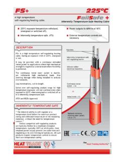
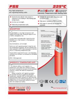
5 Selection of heat tracer The design , Installation , Commissioning and For a particular application, there are some basic Maintenance of electric heat tracing systems shall design characteristics that shall be reviewed to conform to all IEC requirements for the use of determine the choice of trace heater(s). These electrical equipment and with the requirements of are as follows:- the relevant heat tracing standard, usually either a) The maximum withstand temperature of the IEC 62395 Electrical resistance trace heating heat tracers shall be greater than the maximum systems for industrial and commercial applications possible work piece temperature (which may be or IEC 60079-30 Explosive atmospheres - electrical greater than the normal operating temperature). resistance trace heating. Consideration shall and must be greater than the maximum maintain be given to the Maintenance of the system and temperature.
6 Process equipment, to energy efficiency, and to testing of the installed system for operational b) Heat tracers should be suitable for operation satisfaction and safety. in the environmental conditions specified, for example, a corrosive atmosphere or a low ambient Note: temperature. A copy of any Heat Trace ATEX certificate or any c) For hazardous locations, heat tracers must be other approvals certificate can be provided on certified for use in the particular explosive gas request. atmosphere. When designing a heat tracing system for use in For any application, there is a maximum allowable explosive gas atmospheres, additional constraints power density at which a heat tracer can be used are imposed due to the requirements and without damaging either the work piece or its classification of the area under consideration.
7 Contents. This is particularly critical in certain The heat tracing selection shall consider the cases, such as with lined pipes, vessels containing determination of the maximum possible system caustic soda or with heat-sensitive materials. temperature (usually the heater outer sheath The maximum allowable power density shall be temperature) under worst case conditions recorded in the system documentation. Multiple as specified in IEC 62395 or 60079-30. This tracing or spiralling of a single heat tracer may be temperature may be reduced, for example, required. through adjustments to the system parameters, for instance by the use of multiple tracers to reduce the power produced per unit length. The excess of installed power over and above the heating duty requirements, and the way in which heat tracers are applied, installed and operated shall not be the cause, even under worst-case conditions, of any unacceptable risk.
8 1. Site-fabricated heaters When multiple heat tracers (especially on pipes with different flow conditions) are Site-fabricated heat tracers are permissible grouped together under a single surface-sensing provided that: temperature control device, each design condition shall be analysed as a stabilised design . - Installation personnel are competent in the special techniques required. - heat tracers pass the field (site work) test Inherently temperature-safe heat requirements. tracers (PTC characteristic). - heat tracers are correctly marked in Heat tracers that significantly reduce power accordance with the heat tracing standards. with an increase in temperature may be deemed inherently temperature-safe if their power output Maximum temperature determination is practically zero at a sheath temperature less It is important that the maximum sheath than the maximum withstand temperature of temperature of the heat tracer is determined for the heater.
9 Thus, in most applications further all applications to ensure safety from overheating. temperature limiting control measures are not Some examples are: necessary, provided that this sheath temperature is also below any other high limit temperature, a) Applications such as non-metallic piping where such as the maximum allowable process the maximum temperature of the heat tracer may temperature, or the T- class if the application is exceed the maximum withstand temperature of in an hazardous location. However, temperature the pipe material, the thermal insulation, or other controls may be utilised for energy efficiency components of the system; purposes. b) Applications that are not thermostatically It should be noted that ALL Heat Trace's range controlled or have ambient sensing control, of self-regulating heating cables are Inherently and that have potentially high heater sheath Temperature-Safe (IT-S) and rarely require temperatures at equilibrium; temperature controls to ensure temperature c) Critical applications where a high degree of safety.
10 Process temperature accuracy is required; Note: In determining the maximum sheath temperature Clearly, Inherently Temperature-Safe (IT-S) heat it should be assumed that the controlling tracers provide the SAFEST form of temperature- thermostat has failed in the on' position. The safe protection and should ALWAYS be selected determined maximum heater sheath temperature as a first option from a safety standpoint, as IT-S. must not exceed the high limit temperature for neither relies on a designer's calculations, nor the the application. This high limit temperature reliability of a temperature controller. may, for example, be the maximum withstand temperature of the heater, a process temperature limit, or, if in a hazardous area, the Temperature Class of the hazard. There are three ways of protecting the heat tracing system from exceeding the high-limit temperature:- 1.