Transcription of Design, Modelling & Analysis of Double Wishbone …
1 International Journal on Mechanical Engineering and Robotics (IJMER) _____ _____ ISSN (Print) : 2321-5747, Volume-4, Issue-1,2016 58 Design, Modelling & Analysis of Double Wishbone Suspension System 1 Nikita Gawai, 2 Deepak Yadav, 3 Shweta Chavan, 4 Apoorva Lele, 5 Shreyash Dalvi Thakur College of Engineering & Technology, Kandivali (E), Mumbai-400101. Email: Abstract : The main objective of the project is to analyze the entire Double Wishbone suspension system for Green F1 car, as it allows the engineer to carefully control the motion of the wheel throughout suspension travel. A 3D CAD model of the Double Wishbone is prepared by using SolidWorks (CAD Software) for analyzing the system capable of handling Green F1 car while maintaining the ride quality.
2 The topic is focused on designing the above mentioned suspension system considering the dynamics of the vehicle along with minimizing the unsprung mass. Index Terms Roll center, Stiffness, Spring, Strut, Sprung , Wishbone . I. INTRODUCTION Suspension system is the term given to the system of springs, shock absorbers and linkages that connect a vehicle to its wheels. When a tire hits an obstruction, there is a reaction force and the suspension system tries to reduce this force. The size of this reaction force depends on the unsprung mass at each wheel assembly. In general, the larger the ratio of sprung weight to unsprung weight, the less the body and vehicle occupants are affected by bumps, dips, and other surface imperfections such as small bridges.
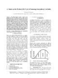
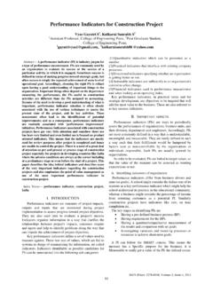
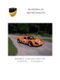
3 A large sprung weight to unsprung weight ratio can also impact vehicle control. Double Wishbone Suspension System consists of two lateral control arms (upper arm and lower arm) usually of unequal length along with a coil over spring and shock absorber. : Double Wishbone Suspension system It is popular as front suspension mostly used in rear wheel drive vehicles. Design of the geometry of Double Wishbone suspension system along with design of spring plays a very important role in maintaining the stability of the vehicle. The upper arm is usually shorter to induce negative camber as the suspension jounces (rises), and often this arrangement is titled an "SLA or Short Long Arms suspension. When the vehicle is in a turn, body roll results in positive camber gain on the lightly loaded inside wheel, while the heavily loaded outer wheel gains negative camber.
4 The Four bar link mechanism formed by the unequal arm lengths causes a change in the camber of the vehicle as it rolls, which helps to keep the contact patch square on the ground, increasing the ultimate cornering capacity of the vehicle. It also reduces the wear of the outer edge of the tire. II. PROCEDURE FOR DESIGN The design procedure for the chosen suspension system is divided into two stages: 1. Primary design: Basic design and development of suspension system components. Modified design parameters based on approximation of dynamic condition. Static testing and Analysis . 2. Secondary design:- Dynamic testing and Analysis on ANSYS. Modification of design parameters based on dynamic testing results. International Journal on Mechanical Engineering and Robotics (IJMER) _____ _____ ISSN (Print) : 2321-5747, Volume-4, Issue-1,2016 59 The following components are to be design:- 1.
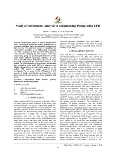
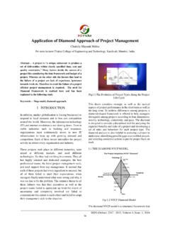
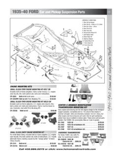
5 Suspension Spring 2. Wishbones III. DESIGN 1. Suspension spring: Type of spring : Helical spring [2] Advantages of helical spring: Easy to manufacture & High reliability Deflection of spring is linearly proportional to the force acting on the spring Less expensive than others type of springs Sprung mass = 350 kg (approx.) Factor for static to dynamic conditions: 3 According to the mass distribution of 60:40 (Rear: Front) Mass per wheel (Front) = 70 kg Mass per wheel (Rear) = 105 kg 1) Front spring Angle of inclination of the strut = 60 (from horizontal) Point of attachment of strut = 10 (254mm) from chassis end .. (from suspension geometry) Reaction force acting from the ground on the wheel = (Mass per wheel * ) N = (70kg * ) N = N Wishbone wheel centerline A Forces on front Wishbone Considering the Wishbone hinges(A) as the point about which moment is taken; Horizontal distance of reaction force from hinge point = ( ).
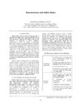
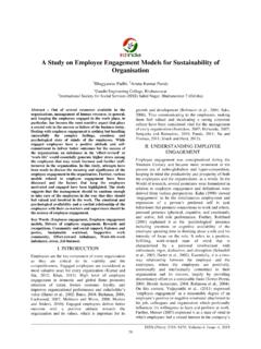
6 From suspension geometry Horizontal distance of strut attachment point from hinge point = ( ) By taking moment about hinge points: * = Spring Force * Spring Force = N Considering the dynamic factor, Dynamic force acting on the spring = N According to the ride conditions and road quality for Green F1, it is concluded that the optimum spring travel should be approx. 4 ( mm) Hence, Required Spring Stiffness =Dynamic Spring Force / Spring Deflection = = N /mm 35 N/mm 2) Rear spring Angle of inclination of the strut = 80 (from horizontal) Point of attachment of strut = ( mm) from chassis end ..(from suspension geometry) Reaction force acting from the ground on the wheel = (Mass per wheel * ) N = (105 kg * ) N = N Wishbone wheel centerline A Forces on rear Wishbone Considering the Wishbone hinges (A) as the point about which moment is taken; Horizontal distance of reaction force from hinge point = Vertical component of spring force Vertical component of spring force 0 International Journal on Mechanical Engineering and Robotics (IJMER) _____ _____ ISSN (Print) : 2321-5747, Volume-4, Issue-1,2016 60 14 ( ).
7 (from suspension geometry) Horizontal distance of strut attachment point from hinge point = ( ) By taking moment about hinge points: * 14 = Spring Force * Spring Force = N Considering the dynamic factor, Dynamic force acting on the spring = N According to the ride conditions and road quality for Green F1, it is concluded that the optimum spring travel should be approx. 4 ( mm) Hence, Required Spring Stiffness =Dynamic Spring Force / Spring Deflection = = N /mm 50N/mm From above calculation we get: Stiffness = 50N/mm Maximum spring force = N Material: Oil hardened steel wire of Grade-4 [3] Ultimate tensile strength = 1100N/mm2 Modulus of rigidity= 81370 N/mm2 According to Indian Standard 4454-1981, Shear stress= *Ultimate tensile strength Shear stress( )=550N/mm2 Taking spring index (C) =8 By wahl s factor, = So, 28dPCk Wire diameter (d) = 9mm Mean coil diameter (D) = C*d = 72mm No.
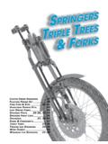
8 Of active coils (N): 438 GdNPD N= 12 coils Assuming that the spring has square and ground ends Nt = N+2 =14 coils Solid length of spring = Nt*d = 126mm Total axial gap = (Nt 1)*1 =13mm Free length = (Solid length + Gap + ) = Pitch of coil = Table 1. Spring dimensions Sr. No. Parameter Suspension ( Front/ Rear) 1. Material Grade 4 oil hardened spring steel 2. Wire diameter 9mm 3. Mean coil diameter 72mm 4. Total number of turns 14 5. Free length of spring 6. Pitch of coil 7. Solid Length 126mm 8. Stiffness 50 N/mm International Journal on Mechanical Engineering and Robotics (IJMER) _____ _____ ISSN (Print) : 2321-5747, Volume-4, Issue-1,2016 61 : 2D of designed Spring Analysis of Spring: Spring is analyzed in Ansys Analysis software so as to determine the actual maximum deflection of spring corresponding to the maximum spring force.
9 Also, the maximum stress value corresponding to the maximum spring force is determined. Table 6: Spring Analysis Results Parameter Value Maximum Force 1700 N Maximum Deflection 110mm Maximum Stress N/mm2 Figure 5: Analysis of Spring in Ansys Determination of Roll Centre: Roll Centre in the vehicle is the point about which the vehicle rolls while cornering. There are two types of roll centres- the geometric roll centre and force based roll centre. The roll centre is the notional point at which the cornering forces in the suspension are reacted to the vehicle body. The location of the geometric roll centre is solely dictated by the suspension geometry, and can be found using principles of the instant centre of rotation.
10 [4] Determination of roll centre plays a very important role in deciding the Wishbone lengths, tie rod length and the geometry of wishbones. Roll centre and ICR is determined because it is expected that all the three elements- upper Wishbone , lower Wishbone and tie rod should follow the same arc of rotation during suspension travel. This also means that all the three elements should be displaced about the same centre point called the ICR. Initially, Wishbone lengths are determined based on track width and chassis mounting. These two factors- track width and chassis mounting points are limiting factors for Wishbone lengths. Later, the position of the tire and the end points of upper arm and lower arm are located. : Roll center in static condition The vehicle centre line is drawn.