Transcription of Design No. U408 - Telling Industries
1 - Fire Resistance Ratings - ANSI/UL 263 +263&objid=1074330469&cfgid=1073741824&v ersion=versionless&parent_id=1073984818& sequence=1[8/8/2013 8:32:32 AM] Design No. Resistance Ratings - ANSI/UL 263 Page BottomDesign/System/Construction/Assembl y Usage DisclaimerAuthorities Having Jurisdiction should be consulted in all cases as to the particular requirements covering the installationand use of UL Certified products, equipment, system, devices, and Having Jurisdiction should be consulted before resistance assemblies and products are developed by the Design submitter and have been investigated by UL forcompliance with applicable requirements. The published information cannot always address every construction nuanceencountered in the field issues arise, it is recommended the first contact for assistance be the technical service staff provided by theproduct manufacturer noted for the Design .
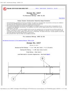
2 Users of fire resistance assemblies are advised to consult the general GuideInformation for each product category and each group of assemblies. The Guide Information includes specifics concerningalternate materials and alternate methods of products which bear UL's Mark are considered Ratings - ANSI/UL 263 See General Information for Fire-resistance Ratings - ANSI/UL 263 Design No. U408 February 19, 2013 Nonbearing Wall Rating 2 Hr1. Floor and Ceiling Runners (Not Shown) - Channel shaped, 3-1/2 in. (min) deep, with min 1-1/4 legs, fabricated from min 25 MSG corrosion-protected steel, attached to floor and ceiling with fasteners 24in. OC Framing Members* - Floor and Ceiling Runner Not shown - In lieu of Item 1 For use with Item2A, proprietary channel shaped runners, 1-1/4 in.
3 Deep by min 3-1/2 in. wide fabricated from min galv steel, attached to floor and ceiling with fasteners spaced 24 in. OC EXPANDED METAL PRODUCTS CO Viper20 TrackMARINO/WARE, DIV OF WARE Industries INC Viper20 TrackHome Quick Guide Contact Us - Fire Resistance Ratings - ANSI/UL 263 +263&objid=1074330469&cfgid=1073741824&v ersion=versionless&parent_id=1073984818& sequence=1[8/8/2013 8:32:32 AM]PHILLIPS MFG CO L L C Viper20 Track1B. Framing Members* Floor and Ceiling Runners Not shown - In lieu of Item 1 For use with Item2B, channel shaped runners, 1-1/4 in. deep by min 3-1/2 in. wide fabricated from min in. thick galvsteel, attached to floor and ceiling with fasteners spaced 24 in.
4 OC BUILDING SYSTEMS CD ProTRAKDMFCWBS L L C ProTRAKMBA BUILDING SUPPLIES ProTRAKRAM SALES L L C Ram ProTRAKSOUTHEASTERN STUD & COMPONENTS INC ProTRAKSTEEL STRUCTURAL SYSTEMS L L C Tri-S ProTRAK1C. Framing Members* - Floor and Ceiling Runner Not shown - In lieu of Item 1 For use with Item2C, proprietary channel shaped runners, 1-1/4 in. deep by min 3-1/2 in. wide fabricated from min galv steel, attached to floor and ceiling with fasteners spaced 24 in. OC Industries L L C Viper20 Track1D. Framing Members* Floor and Ceiling Runners Not shown - In lieu of Item 1 For use with Item2D, channel shaped runners, 1-1/4 in. deep by min 3-1/2 in.
5 Wide fabricated from min in. thick galvsteel, attached to floor and ceiling with fasteners spaced 24 in. OC Industries L L C TRUE-TRACK 2. Steel Studs Channel shaped, min 3-1/2 in. deep, 1-1/4 in. flanges and 3/16 in. returns, fabricated frommin 25 MSG corrosion-protected steel, spaced a max of 24 in. OC. Studs to be cut 5/8 in. less than assemblyheight and friction-fit in Framing Members* - Steel Studs Not shown - In lieu of Item 2 For use with Item 1A, proprietarychannel shaped steel studs, 1-1/4 in. deep by min 3-1/2 in. wide fabricated from min in. thick galv cut 5/8 in. less in length than assembly EXPANDED METAL PRODUCTS CO Viper20 MARINO/WARE, DIV OF WARE Industries INC Viper20 PHILLIPS MFG CO L L C Viper20 2B.
6 Framing Members* Steel Studs Not shown - In lieu of Item 2 For use with Item 1B,channelshaped steel studs, min 3-1/2 in. wide fabricated from min in. thick galv steel, spaced a max of 24 Studs cut 5/8 in. less in length than assembly BUILDING SYSTEMS CD ProSTUDDMFCWBS L L C - Fire Resistance Ratings - ANSI/UL 263 +263&objid=1074330469&cfgid=1073741824&v ersion=versionless&parent_id=1073984818& sequence=1[8/8/2013 8:32:32 AM]MBA BUILDING SUPPLIES ProSTUDRAM SALES L L C Ram ProSTUDSOUTHEASTERN STUD & COMPONENTS INC ProSTUDSTEEL STRUCTURAL SYSTEMS L L C Tri-S ProSTUD2C. Framing Members* - Steel Studs Not shown - In lieu of Item 2 For use with Item 1C, proprietarychannel shaped steel studs, 1-1/4 in.
7 Deep by min 3-1/2 in. wide fabricated from min in. thick galv cut 5/8 in. less in length than assembly Industries L L C Viper20 2D. Framing Members* Steel Studs Not shown - In lieu of Item 2 For use with Item 1D, channelshaped steel studs, min 3-1/2 in. wide fabricated from min in. thick galv steel, spaced a max of 24 Studs cut 5/8 in. less in length than assembly Industries L L C TRUE-STUD 3. Batts and Blankets* (Optional) Placed in stud cavities, any glass fiber or mineral wool insulationbearing the UL Classification Marking as to Surface Burning Characteristics and/or Fire Batts and Blankets (BKNV or BZJZ) Categories for names of Classified Gypsum Board* Gypsum panels with beveled, square or tapered edges.
8 Base layer applied vertically orhorizontally on both sides of the studs, with vertical joints centered over studs and staggered one stud cavityon opposite sides of studs. Horizontal edge joints (when applied horizontally) and horizontal butt joints (whenapplied vertically) on opposite sides of studs need not be staggered or backed. Base layer panels attached tostuds with 1 in. long Type S crews spaced 8 in. OC when applied horizontally, or 8 in. OC along the verticaledges and 12 in. OC in the field when applied vertically. Remaining two layers applied vertically or horizontallyon one side of the wall. Horizontal butt joints staggered a min of 6 in. on adjacent layers.
9 First of these twolayers attached to studs with 1-5/8 in. long Type S screws spaced 12 in. OC. Face layer attached to studs with2-3/8 in. Type S screws spaced 8 in. OC when applied horizontally, or 8 in. OC along the vertical edges and 12in. OC in the field when applied vertically. When used in widths other than 48 in., gypsum panels to beinstalled INC 5/8 in. thick Type AR, C, IP-AR, IP-X1, IP-X2, IPC-AR, SCX, SHX, WRX or STATES GYPSUM CO 5/8 in. thick Type AR, C, FRX-G, IP-AR, IP-X1, IP-X2, IPC-AR, SCX, SGX,SHX, WRX, WRC, USGX (Joint tape and compound, Item 5, optional for use with Type USGX).USG MEXICO S A DE C V 5/8 in. thick Type AR, C, IP-AR, IP-X1, IP-X2, IPC-AR, SCX, SHX, WRX, Gypsum Board* (As an alternate to Item 4, not for use with Items 1B and 2B) - Nom 5/8 in.
10 Thickgypsum panels with beveled, square or tapered edges installed as described in Item INC Type ULXUNITED STATES GYPSUM CO Type MEXICO S A DE C V Type ULX5. Joint Tape and Compound Vinyl or casein, dry or premixed joint compound applied in two coats tojoints and screw heads of outer layers. Paper tape, nom 2 in. wide, embedded in first layer of compound - Fire Resistance Ratings - ANSI/UL 263 +263&objid=1074330469&cfgid=1073741824&v ersion=versionless&parent_id=1073984818& sequence=1[8/8/2013 8:32:32 AM]all joints of outer layer panels. When square-edge gypsum board is used, treatment of joints is Caulking and Sealants* (Optional, not shown) - A bead of acoustical sealant applied around thepartition perimeter for sound STATES GYPSUM CO Type AS*Bearing the UL Classification MarkLast Updated on 2013-02-19 Questions?