Transcription of Design of an Instrumentation Amplifier
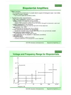
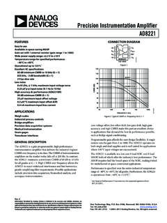
1 Design of an Instrumentation AmplifierECE 480 Spring 2015 Justin BauerExecutive SummaryInstrumentation amplifiers are important integrated circuits when dealing with low voltage situations. This application note will teach the reader how to Design an Instrumentation Amplifier by discussing important characteristics and by deriving a transfer function. 1 IntroductionAn Instrumentation Amplifier is an integrated circuit (IC) that is used to amplify a signal. This type of Amplifier is in the differential Amplifier family because it amplifies the difference between two inputs. The importance of an Instrumentation Amplifier is that it can reduce unwanted noise that is picked up by the circuit. The ability to reject noise or unwanted signals common to all IC pins is called the common-mode rejection ratio (CMRR).
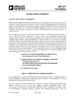
2 Instrumentation amplifiers are very useful due to their high CMRR. Other characteristics, such as high open loop gain, low DC offset and low drift, make this IC very important in circuit amplifiers are used in many different circuit applications. Their ability to reduce noise and have a high open loop gain make them important to circuit Design . Figures 1-3 illustrate several different applications that utilize Instrumentation amplifiers. The Instrumentation amplifiers shown in figures 1-3 are the 1. Bridge AmplifierFigure 2. ECG AmplifierFigure 3. Thermocouple AmplifierObjectiveThe objective of this application note is to instruct circuit designers how to Design and build an Instrumentation Amplifier that will be suitable for any circuit an Instrumentation Amplifier1. Select an Op an appropriate op amp is an important part in designing an Instrumentation Amplifier .
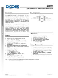
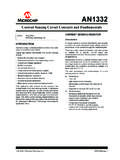
3 The Instrumentation Amplifier will require three op amps. Almost any op amp will work for this Design . However, with circuit size in mind, this Design will use the LM324. The LM324 IC has four op amps on the chip, which will reduce size and amount of wires needed to build the circuit. The LM324 can be seen below in figure 4, illustrating how the four op amps are laid out within the maximum gain of this Amplifier will depend on the input. The LM324 op amp will begin to saturate at VCC V. If the input multiplied by the gain is above this value, the op amp will saturate and give an incorrect 4. LM324 IC2. Select Resistor Values4A typical Instrumentation Amplifier will have seven resistors. These resistors are oriented between the op amps as shown in figure 5. Instrumentation amplifiers are unique in the fact that resistor values can be selected so that onlyone resistor will dictate the overall gain.
4 This can be done if all other resistor values are chosen properly. The transfer function of a typical Instrumentation Amplifier is: Vout= (V1 V2)(R2/R1)(1+2R5/RG)This is the case if R5= R6, R2= R4and R1= R3. However, this transfer function can be simplified further if R2= R4 = R1= R3 = R5= R6 = R. The transfer function would then become:Vout= (V1 V2)(1+2R/RG)This transfer function allows the gain to be decided by one resistor, RG. Finally, in order to allow large gain, select R to be between 25 KOhm and 1 MOhm. For this application note R will be selected to be 25 5. Instrumentation Amplifier Schematic3. Calculating GainWith R selected to be 25 KOhm the overall transfer function will be:Vout= (V1 V2)(1+50K/RG)This simplifies the transfer function and allows one resistor (RG) to decide the overall gain.
5 The smaller resistor selected for RGwill create a large gain, while a large resistor will create a small gain. Table 1 gives examples of different gain values and their associated 1. Gain and Resistor Values6 For this application note, a gain of 10 was selected,which would make RG a value of KOhm. Testing the DesignTo ensure the Design is working properly, it must be tested. In order to test the circuit, a few different lab machines are required, such as: an oscilloscope, a function generator and two power supplies. First, one must set the power supplies to +15 V and -15 V. This is the typical operation voltage for the LM324 op amp. Next, the circuit should be built on a breadboard so that it is easy to interchange components. The pin-out for the LM324 is shown in figure 4. Once the circuit is built, set the function generator to a 500 mVppSIN wave at 1 KHz and input it to V1, as shown in figure 5.
6 Also, one must ground the other input terminal. In order to test the gain of the Instrumentation amp, one must place an oscilloscope scope probe on the function generator and another on the output of the 7amplifier. With the power supplied to the circuit and a proper waveform as an input, one should see an output similar to figure 6. Figure 6 displays the input and the output on the same time scale, but different voltage scales. To ensure the gain is about 10, take the output voltage and divide it by the input voltage. This example has Vout/Vin= mV = 6. Input (Top Waveform) and Output (Bottom Waveform)ConclusionInstrumentation amplifiers are easy to Design IC s that can be used in many applications. The characteristic that makes Instrumentation amplifiers important is their ability to reduce outside noise.
7 The ability to reduce noise is essential in applications where the input voltage is very small (microvolt range).The simplicity of the Design depends on the selection of the resistor values. If chosen correctly, the gain can be calculated and changed with one resistor. This will 8help prototyping costs by eliminating the need to have several different resistor