Transcription of DESIGN OF AXIALLY LOADED COLUMNS - steel-insdag.org
1 DESIGN OF AXIALLY LOADED COLUMNS 10 DESIGN OF AXIALLY LOADED COLUMNS INTRODUCTION In an earlier chapter, the behaviour of practical COLUMNS subjected to axial compressive loading was discussed and the following conclusions were drawn. Very short COLUMNS subjected to axial compression fail by yielding. Very long COLUMNS fail by buckling in the euler mode. Practical COLUMNS generally fail by inelastic buckling and do not conform to the assumptions made in euler theory. They do not normally remain linearly elastic upto failure unless they are very slender Slenderness ratio ( /r) and material yield stress (fy) are dominant factors affecting the ultimate strengths of AXIALLY LOADED COLUMNS .
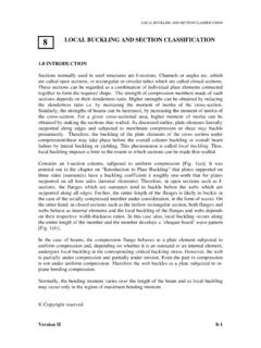
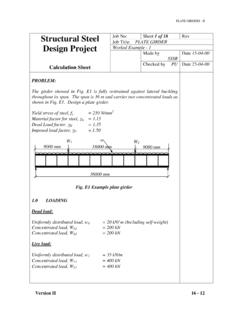
2 The compressive strengths of practical COLUMNS are significantly affected by (i) the initial imperfection (ii) eccentricity of loading (iii) residual stresses and (iv) lack of defined yield point and strain hardening. Ultimate load tests on practical COLUMNS reveal a scatter band of results shown in Fig. 1. A lower bound curve of the type shown therein can be employed for DESIGN purposes. x xSlenderness ( /r) 50 100 150 c (Mpa) Test data (x) from collapse tests on practical COLUMNS euler curve DESIGN curve x x x x x x x x x x x x x x x x x fy 200 100 Fig.
3 1 Typical column DESIGN curve Copyright reserved Version II 10 - 1 DESIGN OF AXIALLY LOADED COLUMNS HISTORICAL REVIEW Based on the studies of Ayrton & Perry (1886), the British Codes had traditionally based the column strength curve on the following equation. ()1()()cececyf = where fy = yield stress c = compressive strength of the column obtained from the positive root of the above equation e = euler buckling stress given by (1a) 22 E = a parameter allowing for the effect of lack of straightness and eccentricity of loading.
4 = Slenderness ratio given by ( /r) In the deviation of the above formula, the imperfection factor was based on )2(2ry = where y = the distance of centroid of the cross section to the extreme fibre of the section. = initial bow or lack of straightness r = radius of gyration. Based on about 200 column tests, Robertson (1925) concluded that the initial bow ( ) could be taken as length of the column/1000 consequently is given by )3(. = = =rrry where is a parameter dependent on the shape of the cross section.
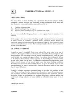
5 Version II 10 - 2 DESIGN OF AXIALLY LOADED COLUMNS c(Mpa) fy euler curve DESIGN curve with = 200 00 1 50 100 150 Robertson s DESIGN Curve Robertson evaluated the mean values of for many sections as given in Table 1: Table1: values Calculated by Robertson Column type Values Beams & COLUMNS about the major axis Rectangular Hollow sections Beams & Universal COLUMNS about the minor axis Tees in the plane of the stem He concluded that the lower bound value of = was appropriate for column designs.
6 This served as the basis for column designs in Great Britain until recently. The DESIGN curve using this approach is shown in Fig. 2. The DESIGN method is termed "Perry-Robertson approach". MODIFICATION TO THE PERRY ROBERTSON APPROACH Stocky COLUMNS It has been shown previously that very stocky COLUMNS ( stub COLUMNS ) resisted loads in excess of their squash load of ( theoretical yield stress multiplied by the area of the column). This is because the effect of strain hardening is predominant in low Version II 10 - 3 DESIGN OF AXIALLY LOADED COLUMNS values of slenderness ( ).
7 Equation (1) will result in column strength values lower than fy even in very low slenderness cases. To allow empirically for this discrepancy, recent British and European Codes have made the following modification to equation 3 given by = In the unmodified form this will cause a drop in the calculated value of column strength even for very low values of slenderness. Such COLUMNS actually fail by squashing and there is no drop in observed strengths in such very short COLUMNS .
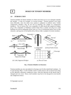
8 By modifying the slenderness, to ( - 0) we can introduce a plateau to the DESIGN curve at low slenderness values. In generating the British DESIGN (BS: 5950 Part-1) curves was used as an appropriate fit to the observed test data, so that we () =obtain the failure load (equal to squash load) for very low slenderness values. Thus in calculating the elastic critical stress, we modify the formula used previously as follows: ())4(0202 > =ofvaluesallforEe Note that no calculations for e is needed when e as the column would fail by squashing at fy.
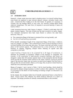
9 0[ (E/fy )1/2] Test data (x) from collapse tests on practical COLUMNS euler curve Robertson s curve c(Mpa) fyxx x x x x xxx x x x x xx x x x x xx 200 100 50 100 Strut curve with a plateau for low slenderness values Version II 10 - 4 DESIGN OF AXIALLY LOADED COLUMNS Influence of Residual Stresses Reference was made earlier to the adverse effect of locked-in residual stresses on column strengths (see Fig. 4). Studies on COLUMNS of various types carried out by the European Community have resulted in the recommendation for adopting a family of DESIGN curves rather than a single Typical DESIGN Curve shown in Fig.
10 3. Typically four column curves are suggested in British and European codes for the different types of sections commonly used as compression members [See Fig. 5(a)]. In these curves, = ( - 0) where and the values are varied corresponding to various sections. yfE 0= Thus all column designs are to be carried out using the strut curves given in [Fig. 5(a)]. Version II 10 - 5 4 Distribution of residual stresses C T C Rolled beam C Welded box TT T T T C CC CTTTT C T C Rolled columnC T (Curve A) (Curve B) (Curve C) (Curve D) a) = b) = c) = d) = 050100150200250300fyCompressive strength c (Mpa) C C C050100150200250 Slenderness, Fig.