Transcription of Design of Centrifugal Pump Volute-Type Casing
1 International Journal of Science and Engineering Applications Volume 8 Issue 08,325-330, 2019, ISSN:-2319 7560 325 Design of Centrifugal Pump Volute-Type Casing Khin Sandi Cho Department of Mechanical Engineering Technological University Hpa-an, Myanmar Aye Thida San Department of Mechanical Engineering Technological University Patein, Myanmar Soe Myat Thu Department of Mechanical Engineering Technological University Mawlamyine, Myanmar Abstract: Every Centrifugal pump has four main components, namely, Casing , impeller, suction pipe and discharge pipe. The important principles and fluid mechanics theories on Centrifugal pump are introduced in firstly. The detailed Design procedure for volute type pump Casing is carried out. In this paper, various kinds of pumps and operational sequences are described. And then, application and characteristics of Centrifugal pump are also expressed.
2 This paper relates to the Design of Casing of single-suction Centrifugal pump that can develop a head of 30m and discharge of water at the speed of 1880 rpm. The designed impeller has 115 mm inlet diameter, 256 mm outlet diameter, inlet vane angle and outlet vane angle. The number of vanes is 6. The outlet width is 15mm. The discharge diameter is 3in (96mm) to operate the designed head and capacity. The maximum efficiency of the pump is 72 %. The designed single-suction Centrifugal pump can fulfil the requirements of agricultural processes. Keywords: Centrifugal pump; Fluid mechanic; Volute type Casing ; Single-suction pump; Pump Casing Design . 1. INRODUCTION Centrifugal pump is the device for converting of mechanical energy of the drive shaft to hydraulic energy of the handling fluid to get it to the required place or height by the Centrifugal force of the impeller blade and the change in pressure and velocity in the volute Casing .
3 The input power for Centrifugal pump is the mechanical energy of the drive shaft driven by the prime mover such as electrical motor. The output energy is hydraulic energy of the fluid being raised or carried. So, its purpose is to provide the necessary pressure to move the fluid at the desired rate. The Centrifugal pump moves liquid by rotating one or more impellers inside a volute Casing . The liquid is introduced through the Casing inlet to the eye of the impeller where it is picked up by the impeller vanes. The rotation of the impeller at high speeds creates the Centrifugal force that throws the liquid along the vanes, causing it to be discharged from its outside diameter at a higher velocity. This velocity energy is converted to pressure energy by the volute Casing prior to discharging the liquid to the system.
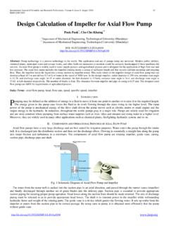
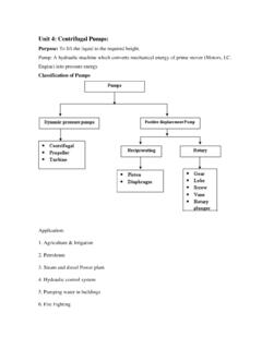
4 2. GENERAL DESCRIPTION OF Centrifugal PUMP The Centrifugal pump is so called because the pressure increase within its rotor due to Centrifugal action is an important factor in its operation. Figure 1. Single-suction Centrifugal Pump In the single suction pump, the water enters the impeller from only one side. Because of this action, a single-suction Centrifugal pump impeller is exposed to a large axial hydraulic thrust force resulting from the unbalanced hydraulic pressure on the impeller. This force tends to move the impeller away from the suction side. Figure 1 shows a single-suction pump. Volute-Type Centrifugal Pump Casing In a volute Casing , the impeller discharges into a single Casing channel of gradually increasing area called a volute, and the major part of the conversion takes place in the conical discharge nozzle.
5 The volute Centrifugal pump has no diffusion vane but instead of the Casing and is of a spiral type. The Casing is as shown in Figure 2 . So it makes as to produce an equal velocity of flow at all sections around the circumference and also to gradually reduce the velocity of the water as it flows from the impeller to the discharge pipe. The spiral is often called the nozzle. A Centrifugal pump volute increases in area from its initial point until it encompasses the full 360 degrees around the impeller and then flares out to the final discharge opening. The wall dividing the initial section and the discharge nozzle portion of the Casing called the tongue of the volute, or the cut-water. Figure 2. Volute Casing International Journal of Science and Engineering Applications Volume 8 Issue 08,325-330, 2019, ISSN:-2319 7560 326 3.
6 Design CONSIDERATION OF CENT-RIFUGAL PUMP VOLUTE Casing The hydraulic Design of an end section single-stage Centrifugal pump Casing for fresh water is considered by the following: Specific Speed Using equation, we can calculate the specific speed, ns (rpm) is considered, 3/4 HQnsn (1) Pump efficiency is assumed by using Figure 3 . And also the diameter of suction pipe Ds (or ds) can be estimated from this chart. The discharge pipe diameter Dd (or dd) is usually selected equal to or one size smaller than that of the suction pipe. Thus, velocities in these pipes are given by 4sD sQsV2 (2) 4D sQdV2d (3) The inner diameter, ID corresponding to Ds or Dd shown in Table 1 is substituted for Ds or Dd in the above equations to calculate each of these velocities.
7 Input Power The input power, L (W) is considered by gHs QL (4) Rated output of an electric motor, Lr (KW) is decided from the following equation. 1000tr L)aF(1L (5) Where, Fa is the allowance factor, and for an electric motor and larger than for engines. tr is the transmission efficiency, and for direct coupling and for belt drive. If an electric motor is used for driving a pump, Table 2 is used for its selection. Hub and Shaft Diameters The diameter of the end of main shaft dc is calculated from the next equation. 3nhLk3al (6) The shaft diameter at the hub section dsh is selected so as to satisfy dsh > dc. The dimension of hub at the impeller eye are usually decided from Diameter: Dh = ( ) dsh Length: Lh = ( ) dsh The diameter of impeller eye Do is calculated from the following equation.
8 2hDmo Vs4 QoD (7) Where the velocity at the eye section is given by Vmo = Kmo2gH= ( ) Vm1 (8) Kmo = ( ) + Impeller Stepanoff Chart The stepanoff chart shown in Figure 5 is widely used to decide the impeller geometry. If the blade outlet angle b2 near is selected. The parameters Ku (speed constant), Km1, Km2, and 21 DDare obtained, since ns is given. Thus, U2 = Ku2gH (9) Vm1 = Km12gH (10) Vm2 = Km22gH (11) Impeller Outlet The outlet diameter D2 is decided considering the following relationship; n 60UD22 (12) The blade exit angle is set by the following, b2 = (15 deg 35 deg) Impeller Inlet The inlet diameter is considered from D1 = D2 21DD.
9 Thus, the peripheral velocity at the inlet is: U1 =60n D1 (13) The blade inlet angle b1 (deg) is considered by, b1=tan-1 1m1b1 UVK tan-1 1m1UV+(0 6) (14) where, Kb1= Blade number The number of impeller blade Z is decided by the following, 2 (15) When the impeller is made of bronze ( BC6), the minimum blade thickness is mm and shroud thickness is mm for an impeller having the diameter less than 200 mm. They are and mm respectively, if D2 is greater than 200 mm. Equation International Journal of Science and Engineering Applications Volume 8 Issue 08,325-330, 2019, ISSN:-2319 7560 327 Passage width The width at the inlet b1 and that of outlet b2 are respectively decided based on the following equations where smooth variation in velocity is considered.
10 (16) b111s in s , b222s in s where, 1 = blade thickness near the leading edge (mm) 2 = blade thickness near the trailing edge (mm) Zs D DV DsQb222m222 (17) Casing Average Flow Velocity in the Volute Casing The average volute velocity Vv is determined from the relationship; 2gHvKvV (18) where , Vv = average flow velocity in the volute Casing (m/s) Kv = experimental Design factor g = gravitational acceleration (m/s2) H = head required (m) So, to find the average flow velocity in the volute at the cut water, it is required to know the values of Kv, required head (H). The gravitational acceleration is m/s2. The value of Kv varies with the specific speed of the Design pump. It is determined by using the Volute Constants Chart as shown in Figure 4.