Transcription of Design of Reinforced Concrete Columns - Colin Caprani
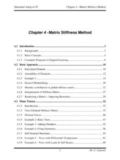
1 Civil Engineering Design (1). Civil Engineering Design (1). Design of Reinforced Concrete Columns 2006/7. Dr. Colin Caprani , Chartered Engineer 1 Dr. C. Caprani Civil Engineering Design (1). Contents 1. Introduction .. 3. 3. Failure Modes .. 5. Design Aspects .. 7. Background 8. 2. Short Braced Axially Loaded 10. 10. Example .. 11. When loaded by Beams .. 12. 3. Short Braced Columns Resisting Axial Load and Moment .. 13. 13. Case 1: h .. 14. Case 2: > h .. 15. Combination of 16. Description of Interaction 18. Example .. 21. Design Using Standard Interaction Diagrams .. 30. 4. Biaxial 33. 33. Method 1 Resolution of 34. Method 2 3-D Interaction 37. Method 3 Code Methods .. 39. Example .. 41. 2 Dr. C. Caprani Civil Engineering Design (1). 1. Introduction Background The two main parameters governing column Design are: Bracing: if the column can sway additional moments are generated through the P effect.
2 This does not affect braced Columns Slenderness ratio: The effective length divided by the lateral dimension of the column. Low values indicate a crushing failure, while high values denote buckling. Bracing The two kinds of bracing are: Braced: Lateral loads on the structure are resisted by elements other than the Columns in the structure; lift cores, shear walls. Hence these Columns mainly take axial load; however, bending moments may result in the Columns due to unsymmetrical arrangements of loads. Unbraced: Lateral loads are resisted by the bending action of the Columns . The axial loads are also taken by the Columns . Slenderness ratio The slenderness ratio is the ratio of the effective length le to the lateral dimension of the column in that direction. We have two directions on plan, and we can have two ratios: Long side of column: slenderness ratio = lex h.
3 Short side of column: slenderness ratio = ley b . 3 Dr. C. Caprani Civil Engineering Design (1). Y. X X. h Y. b Standard Column The effective length is calculated from a table in BS8110 and depends on the end- conditions of the column, for each axis: 4 Dr. C. Caprani Civil Engineering Design (1). Failure Modes We define: Nuz as the crushing load of a perfectly axially loaded column;. N crit as Euler's buckling load for the column. The following graph is typical and shows how for different slenderness ratios, different forms of failure are possible: 5 Dr. C. Caprani Civil Engineering Design (1). From the figure: For l h 15 the crushing capacity is much lower than the buckling capacity and so the column crushes. For l h > 32 the buckling capacity is less than the crushing capacity and so the column buckles.
4 For l h values in between, the failure mode is not clear and depends on imperfections in the column and the way the load is applied. Therefore, BS8110 defines: Short Columns : l h 15 for a braced column and l h 10 for an unbraced column. These ratios must be met for both axes. Slender Columns : any column not meeting the criteria for short Columns . As this module is short, we will only consider short, braced Columns . 6 Dr. C. Caprani Civil Engineering Design (1). Design Aspects At SLS, the axial compression tends to close up the cracks, which is beneficial. Hence crack widths do not normally need to be checked in Columns (crack widths are checked in beams and slabs in water retaining structures and bridges, but don't need to be for Columns ). Further, deflections do not normally need to be checked in Columns .
5 It is ULS conditions that govern the Design of Columns , , their strength. Areas of reinforcement are given for reference: 2. Cross Sectional areas of groups of bars (mm ). Bar Size (mm) 6 8 10 12 16 20 25 32 40. 1 28 50 79 113 201 314 491 804 1257. 2 57 101 157 226 402 628 982 1608 2513. 3 85 151 236 339 603 942 1473 2413 3770. Number of bars 4 113 201 314 452 804 1257 1963 3217 5027. 5 141 251 393 565 1005 1571 2454 4021 6283. 6 170 302 471 679 1206 1885 2945 4825 7540. 7 198 352 550 792 1407 2199 3436 5630 8796. 8 226 402 628 905 1608 2513 3927 6434 10053. 9 254 452 707 1018 1810 2827 4418 7238 11310. 10 283 503 785 1131 2011 3142 4909 8042 12566. Circumference 7 Dr. C. Caprani Civil Engineering Design (1). Background Information We can carry out a section analysis for Columns just as we do for beams. Review section analysis for beams as precursor to that for Columns .
6 We need to use the material properties from BS8110. As a reminder, we have: Stress-Strain Curve for Steel from BS8110. 8 Dr. C. Caprani Civil Engineering Design (1). Stress-Strain Curve for Concrete from BS8110. Remember that the is to relate cube strength to bending strength and is not a factor of safety (which is m ). 9 Dr. C. Caprani Civil Engineering Design (1). 2. Short Braced Axially Loaded Columns Development The Design of such Columns is straightforward. The ultimate force is the sum of the stress areas of the steel and Concrete : f fy . N uz = cu Ac + Asc m m . For Concrete m = and for steel m = (this is due to change back shortly to ). Therefore we have: N uz = f cu Ac + f y Asc Because this relies on a perfect axial load which is virtually impossibly to achieve in practice, a small allowance for an eccentricity of is made to give: N uz = f cu Ac + f y Asc For a rectangular section this is equal to: N uz = f cu bh + Asc ( f y f cu ).
7 Notice that we have effectively reduced the stress in the steel to account for the Concrete that isn't present, but which we have allowed for in the first term. We will do this again. 10 Dr. C. Caprani Civil Engineering Design (1). Example Problem A short braced column is 300 mm square and supports 1700 kN at the ultimate limit state. The characteristic material strengths are f y = 400 N/mm 2 and f cu = 30 N/mm 2 , Design the steel for the column. Solution 11 Dr. C. Caprani Civil Engineering Design (1). When loaded by Beams Short braced Columns that support an approximately (within 15%) symmetrical arrangement of beams can be Design using: N uz = f cu Ac + f y Asc For a rectangular section this is equal to: N uz = f cu bh + Asc ( f y f cu ). Redesign the previous problem for the case when it is loaded by such beams: 12 Dr.
8 C. Caprani Civil Engineering Design (1). 3. Short Braced Columns Resisting Axial Load and Moment Introduction This problem is not so straightforward. We must account for the various possible positions of the neutral axis, as the bending might be large compared to the axial load. Or indeed, vice-verse, in which case we should get our result for short braced axially-only loaded Columns . Here, we consider the general case for rectangular Concrete Columns subject to moment M and axial load N. Remember: the basis is that the strain diagram is linear, and the ultimate strain of Concrete is cu = . 13 Dr. C. Caprani Civil Engineering Design (1). Case 1: h In this case the equivalent rectangular stress block is inside the section and so part of the section is in compression, and part in tension. This occurs when a relatively small axial force and a large moment are applied.
9 B d' cu Fsc Asc sc Fcc x s = h d N. M. As s Fst Beam Strain Stress/Force Applied Section Diagram Diagram Loads Taking F x = 0 , we see: N = Fcc + Fsc Fst For moment equilibrium,: M about centre line = 0. h s h h . M = Fcc + Fsc d ' + Fst d . 2 2 2 2 . 14 Dr. C. Caprani Civil Engineering Design (1). Case 2: > h In this case the equivalent rectangular stress block is outside the section and so all of the section is in compression. This occurs when a relatively large axial force and a small moment are applied. b d' cu Fsc Asc sc x Fcc h d N. s=h M. As s Fst Beam Strain Stress/Force Applied Section Diagram Diagram Loads Taking F x = 0: N = Fcc + Fsc Fst Moment equilibrium: h h . M = Fsc d ' Fst d . 2 2 . 15 Dr. C. Caprani Civil Engineering Design (1). Combination of Cases Noting that the direction of Fst changes, and taking its positive direction to be that of compression, we combine the two cases: N = Fcc + Fsc Fst h s h h.
10 M = Fcc + Fsc d ' + Fst d . 2 2 2 2 . Thus when Fst is in tension and is negative, we get Case 1. Conversely when it is h s positive and = we get Case 2. 2 2. Forces: The forces in the expressions are derived from stress area: Fcc = f cu bs Fsc = ( f sc f cu ) Asc Fst = ( f s f cu ) As In which the area displaced by the reinforcement has been taken into account by reducing the stress accordingly. Note that for Case 1, the force Fst does not need to be reduced in this manner. The stress at any level z can be got from: x z . z = . x . 16 Dr. C. Caprani Civil Engineering Design (1). Hence, the strain in the most compressed steel is: x d ' d ' . sc = = 1 . x x . And in the least compressed steel is: x d d . s = = 1 . x x . Remember that the strain in the steel is limited to: fy m 460 = = Es 200 103. and at that strain the stress is f y.