Transcription of Design of Shafts - IIT Bombay
1 ME 423: Machine DesignInstructor: RameshSinghDesign of Shafts1ME 423: Machine DesignInstructor: RameshSinghIntroduction Torque and Power Transmission Most of rotary prime movers either motors or turbines use shaft to transfer the power Bearings are required for support Shaft failure analysis is critical2ME 423: Machine DesignInstructor: RameshSinghShaft Design Material Selection (usually steel, unless you have good reasons) Geometric Layout (fit power transmission equipment, gears, pulleys) Failure strength Static strength Fatigue strength Shaft deflection Bending deflection Torsional deflection Slope at bearings and shaft-supported elements Shear deflection due to transverse loading of short Shafts Critical speeds at natural frequencies3ME 423: Machine DesignInstructor: RameshSinghShaft Materials Deflection primarily controlled by geometry, not material Strain controlled by geometry but material has a role in stress Strength, Yield or UTS is a material property.
2 Cold drawn steel typical for d< 3 in. HR steel common for larger sizes. Should be machined all over. Low production quantities: Machining High production quantities: Forming4ME 423: Machine DesignInstructor: RameshSinghShaft Layout Shafts need to accommodate bearings, gears and pulleys which should be specified Shaft Layout Axial layout of components Supporting axial loads (bearings) Providing for torque transmission (gearing/sprockets) Assembly and Disassembly(repair & adjustment) 5ME 423: Machine DesignInstructor: RameshSinghAxial Layout of Components6362 Mechanical Engineering DesignThe geometric configuration of a shaft to be designed is often simply a revision ofexisting models in which a limited number of changes must be made. If there is noexisting Design to use as a starter, then the determination of the shaft layout may havemany solutions.
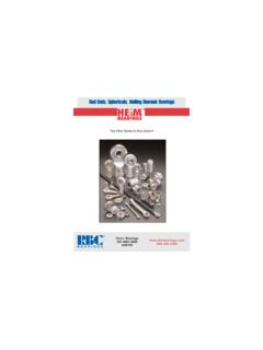
3 This problem is illustrated by the two examples of Fig. 7 2. InFig. 7 2aa geared countershaft is to be supported by two bearings. In Fig. 7 2cafanshaft is to be configured. The solutions shown in Fig. 7 2band 7 2dare not neces-sarily the best ones, but they do illustrate how the shaft-mounted devices are fixed andlocated in the axial direction, and how provision is made for torque transfer from oneelement to another. There are no absolute rules for specifying the general layout, but thefollowing guidelines may be 7 1A vertical worm-gear speedreducer. (Courtesy of theCleveland Gear Company.)Figure 7 2(a) Choose a shaftconfiguration to support andlocate the two gears and twobearings. (b) Solution uses anintegral pinion, three shaftshoulders, key and keyway, andsleeve. The housing locates thebearings on their outer ringsand receives the thrust loads.
4 (c) Choose fan-shaftconfiguration. (d) Solution usessleeve bearings, a straight-through shaft, locating collars,and setscrews for collars, fanpulley, and fan itself. The fanhousing supports the sleevebearings.(a)(b)(c)Fan(d) 12/8/09 12:52PM Page 362 ntt 203:MHDQ196:bud29281:0073529281:bud29281 _pagefiles:ME 423: Machine DesignInstructor: RameshSinghSupporting Axial Load Axial loads must be supported through a bearing to the frame Generally best for only one bearing to carry axial load to shoulder7364 Mechanical Engineering Design Pins Press or shrink fits Tapered fitsIn addition to transmitting the torque, many of these devices are designed to fail ifthe torque exceeds acceptable operating limits, protecting more expensive regarding hardware components such as keys, pins, and setscrewsareaddressed in detail in Sec.
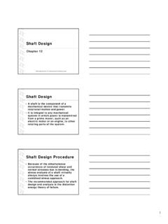
5 7 7. One of the most effective and economical means oftransmitting moderate to high levels of torque is through a key that fits in a groove inthe shaft and gear. Keyed components generally have a slip fit onto the shaft, so assem-bly and disassembly is easy. The key provides for positive angular orientation of thecomponent, which is useful in cases where phase angle timing is 7 3 Tapered roller bearings usedin a mowing machine Design represents goodpractice for the situation inwhich one or more torque-transfer elements mustbe mounted outboard. (Source: Redrawn frommaterial furnished by TheTimken Company.)Figure 7 4A bevel-gear drive in which both pinion and gearare straddle-mounted.(Source: Redrawn frommaterial furnished by Gleason Machine Division.) 12/8/09 12:52PM Page 364 ntt 203:MHDQ196:bud29281:0073529281:bud29281 _pagefiles:364 Mechanical Engineering Design Pins Press or shrink fits Tapered fitsIn addition to transmitting the torque, many of these devices are designed to fail ifthe torque exceeds acceptable operating limits, protecting more expensive regarding hardware components such as keys, pins, and setscrewsareaddressed in detail in Sec.
6 7 7. One of the most effective and economical means oftransmitting moderate to high levels of torque is through a key that fits in a groove inthe shaft and gear. Keyed components generally have a slip fit onto the shaft, so assem-bly and disassembly is easy. The key provides for positive angular orientation of thecomponent, which is useful in cases where phase angle timing is 7 3 Tapered roller bearings usedin a mowing machine Design represents goodpractice for the situation inwhich one or more torque-transfer elements mustbe mounted outboard. (Source: Redrawn frommaterial furnished by TheTimken Company.)Figure 7 4A bevel-gear drive in which both pinion and gearare straddle-mounted.(Source: Redrawn frommaterial furnished by Gleason Machine Division.) 12/8/09 12:52PM Page 364 ntt 203:MHDQ196:bud29281:0073529281:bud29281 _pagefiles:ME 423: Machine DesignInstructor: RameshSinghTorque Transmission Common means of transferring torque to shaft Keys Splines Setscrews Pins Press or shrink fits Tapered fits Keys are one of the most effective Slip fit of component onto shaft for easy assembly Positive angular orientation of component Can Design the key to be weakest link to fail in case of overload8ME 423: Machine DesignInstructor: RameshSinghShaft Design for Stresses Stresses are only evaluated at critical location Critical locations are usually On the outer surface Where the bending moment is large Where the torque is present Where stress concentrations exist9ME 423: Machine DesignInstructor.
7 RameshSinghShaft Stresses Standard stress equations can be customized for Shafts Axial loads are generally small so only bending and torsion will be considered Standard alternating and midrange stresses can be calculated10 Shafts and Shaft Components367 Most Shafts will transmit torque through a portion of the shaft. Typically the torquecomes into the shaft at one gear and leaves the shaft at another gear. A free body dia-gram of the shaft will allow the torque at any section to be determined. The torque isoften relatively constant at steady state operation. The shear stress due to the torsionwill be greatest on outer bending moments on a shaft can be determined by shear and bending momentdiagrams. Since most shaft problems incorporate gears or pulleys that introduce forcesin two planes, the shear and bending moment diagrams will generally be needed in twoplanes.
8 Resultant moments are obtained by summing moments as vectors at points ofinterest along the shaft. The phase angle of the moments is not important since theshaft rotates. A steady bending moment will produce a completely reversed momenton a rotating shaft, as a specific stress element will alternate from compression totension in every revolution of the shaft. The normal stress due to bending momentswill be greatest on the outer surfaces. In situations where a bearing is located at theend of the shaft, stresses near the bearing are often not critical since the bendingmoment is stresses on Shafts due to the axial components transmitted through helicalgears or tapered roller bearings will almost always be negligibly small compared tothe bending moment stress.
9 They are often also constant, so they contribute little tofatigue. Consequently, it is usually acceptable to neglect the axial stresses induced bythe gears and bearings when bending is present in a shaft. If an axial load is appliedto the shaft in some other way, it is not safe to assume it is negligible without check-ing StressesBending, torsion, and axial stresses may be present in both midrange and alternatingcomponents. For analysis, it is simple enough to combine the different types of stressesinto alternating and midrange von Mises stresses, as shown in Sec. 6 14, p. is sometimes convenient to customize the equations specifically for shaft applica-tions. Axial loads are usually comparatively very small at critical locations wherebending and torsion dominate, so they will be left out of the following equations.
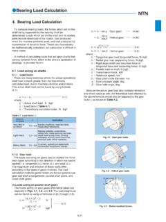
10 Thefluctuating stresses due to bending and torsion are given by a=KfMacI m=KfMmcI(7 1) a=KfsTacJ m=KfsTmcJ(7 2)where Mmand Maare the midrange and alternating bending moments, Tmand Taarethe midrange and alternating torques, and KfandKfsare the fatigue stress-concentrationfactors for bending and torsion, a solid shaft with round cross section, appropriate geometry terms canbe introduced for c, I, and Jresulting in a=Kf32Ma d3 m=Kf32Mm d3(7 3) a=Kfs16Ta d3 m=Kfs16Tm d3(7 4) 12/8/09 12:52PM Page 367 ntt 203:MHDQ196:bud29281:0073529281:bud29281 _pagefiles: Shafts and Shaft Components367 Most Shafts will transmit torque through a portion of the shaft. Typically the torquecomes into the shaft at one gear and leaves the shaft at another gear. A free body dia-gram of the shaft will allow the torque at any section to be determined.