Transcription of DESIGN OF SLAB-ON-GROUND FOUNDATIONS
1 DESIGN OF SLAB-ON-GROUND FOUNDATIONS . A DESIGN , Construction & Inspection Aid For Consulting Engineers August 1981. Prepared for: Copyright, Wire Reinforcement Institute Wire Reinforcement Institute 942 Main Street Hartford, CT 06103. Phone (800) 552-4 WRI [4974]. Fax (860) 808-3009. Authored By: Walter L. Snowden, 2613 Passion Flower Pass Cedar Park, TX 78613. Phone: 512-331-6159. Fax: 512-331-6002. Email: This procedure was developed by Walter L. Snowden, P. E., Consulting Engineer, of Austin, Texas, over a period of some 15 years. It is empirically derived by observing slab performance and writing or modifying equations to give results which approximate the FOUNDATIONS which had been found to give satisfactory results. In addition, Mr.
2 Snowden, has served on the Pre-Stress Concrete Institute Ad Hoc Committee for the development of Tentative Recommendations for Pre-Stressed Slabs-on-Ground and as a Consultant to the Building Research Advisory Board Committee on Residential Slabs-On-Ground. Designs done by this method should be economical yet give quite satisfactory results with a minimum of deflection and resulting superstructure distress. While this publication deals only with FOUNDATIONS reinforced with reinforcing bars and/or welded wire reinforce- ment, the procedure has been developed to be independent of the type of reinforcing used. Wire Reinforcement Institute, Inc. 2003. TF 700-R-07. Table of Contents INTRODUCTION 1. EARLY DEVELOPMENTS 1. SOILS INVESTIGATIONS 2.
3 LABORATORY TESTING 3. DETERMINING THE EFFECTIVE 5. OTHER PARAMETERS 5. WARNING 6. LOADING CONSIDERATIONS 7. SUPPORT CONSIDERATIONS 7. THE SLAB DESIGN 10. BEAM SPACING AND LOCATION 12. SLAB REINFORCING 13. BEAM REINFORCING 13. SITE PREPARATION 14. SLAB FORMING 15. STEEL PLACEMENT 16. SPECIAL CONDITIONS 19. CONCRETE PLACING 20. INSPECTION 22. SHRINKAGE CRACKS 23. APPENDIX A NOTATION. APPENDIX B DESIGN EXAMPLES. APPENDIX C REFERENCES. TF 700-R-07 Page 1. INTRODUCTION cedure, with modifications, has been used for Within the last several years there has been the last 15 years in designing FOUNDATIONS in a lot of interest in a DESIGN procedure for the the southwest with excellent results. DESIGN of light FOUNDATIONS , particularly for use under single family residences.
4 Reports EARLY DEVELOPMENTS. and recommendations have been under- In the early 1950's the use of the monolithic taken and prepared by several study groups reinforced slab foundation become wide- for the purposes of developing DESIGN cri- spread in the south central portion of the teria or extending the Criteria for Selection United States. For the most part there were and DESIGN of Residential Slabs-on-Ground, no consistent standards, and many differ- BRAB Report #33. The recommendations ent versions of this foundation were to be derived from these and other studies vary found throughout the area. Each office of from extremely light to extremely heavy. the Federal Housing Administration had a different version being used in its area, and It was actually the widespread use of the the differences in cross-section and reinforc- post-tensioned SLAB-ON-GROUND which ing were great.
5 Engineers did not have a induced this interest in DESIGN procedure generally accepted procedure to analyze the and in many studies of reported slab failures. slab, and, therefore, the problem was mostly Such reports have; perhaps, created an ignored. over-cautious climate concerning any moves to lighten the DESIGN requirements set forth in In 1955 the Federal Housing Administration BRAB Report #33. Many theoretical analyses together with the National Academy of show that no lessening of the requirements is Science organized a group of nationally emi- possible, while other studies and actual field nent authorities and began a several year installation indicate that considerable vari- research project to develop guidelines for ances are permissible in many areas.
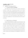
6 DESIGN of SLAB-ON-GROUND FOUNDATIONS . In the DESIGN procedure to be presented The final report, Building Research Advisory herein, adjustments are made to the BRAB Board (BRAB) Report #33 en-titled Criteria procedure which allow the use of this simple for Selection and DESIGN of Residential slab- procedure with larger slabs and further sim- on-ground, was issued in 1968 and was plify the DESIGN engineer's problem of DESIGN - widely discussed by builders. First designs ing an adequate foundation at a reasonable to follow the BRAB Report required foun- cost, both in terms of the engineer's time, dations heavier even than the San Antonio and cost of the installation itself. FHA office standard LAS-22 ( Fig. 1). LAS- 22 was thought to be the heaviest DESIGN The intent of this handbook is to provide a ever needed, but a local study showed it was DESIGN procedure which could be used in any inadequate perhaps 30% of the time.
7 There Consulting engineer's office to give adequate was naturally, great resistance to the added designs for economical construction without costs of DESIGN and construction required by the use of large computers, or the neces- the BRAB Report. sity for site investigations so extensive as to make the use of engineered FOUNDATIONS economically prohibitive. The following pro- TF 700-R-07 Page 2. The next important contribution also oc- slab enjoyed compared to the heavier curred in 1968 when a full scale post-ten- San Antonio Standard Slab . sioned slab was built and tested to destruc- tion. A subsequent report established the Variations from the BRAB Report #33 were feasibility of using post-tensioning in slab-on- developed to maintain a reasonable ratio ground construction and verified many of the between cost of the SLAB-ON-GROUND and the BRAB assumptions.
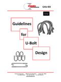
8 Value of the house it supported. The varia- tions presented later in this paper have been In 1965 the writer developed a complete, derived empirically. overall DESIGN system, later modified to con- form, in format, to BRAB Report #33 and fur- SOIL INVESTIGATIONS. ther influenced by the work done by H. Platt It is considered imperative that a soils inves- Thompson, This system gained wide tigation be made on any site on which a use in both Austin and San Antonio because DESIGN is to prepared. of the lower cost which the post-tensioned RESIDENTIAL SLAB-ON-GROUND CONSTRUCTION. FEDERAL HOUSING ADMINISTRATION SAN ANTONIO~ TEXAS INSURING OFFICE. EXTERIOR EXTERIOR INTERIOR ATTACHED GARAGE, BEAM BEAM BEAM CARPORT, PORCH BEAMS. (MASONRY) (FRAME).
9 ALL RESIDENTIAL SLAB-ON- CONCRETE: 2500 PSI MIN. COMPRESSIVE STRENGTH. LAPS. GROUND CONSTRUCTION OR SPLICES: MINIMUM 30 DIAMETERS. SHALL COMPLY WITH THESE SLAB: 4 MINIMUM THICKNESS WITH W OR D9 WIRE 10 . MINIMUMS. VARIATIONS ARE BOTH WAYS. MAXIMUM CLEAR PANEL BETWEEN. ACCEPTABLE WHERE SOIL BEAMS IS 15 : 10 WIDE BY 30 DEEP. (24 . INVESTIGATION OF THE DEEP FOR ATTACHED GARAGE. CARPORT, OR PORCH. BUILDING SITE, CLIMATIC BEAMS) REINFORCE WITH TWO #6 BARS TOP AND TWO. RATINGS, AND ENGINEERING #6 BARS BOTTOM, CONTINUOUS. SPACE ALL STIRRUPS. ANALYSIS INDICATE A SLAB OF 22 ALL BEAMS SHALL PENETRATE MINIMUM 6 INTO. LIGHTER OR HEAVIER DESIGN UNDISTURBED SOIL. IS SUITABLE. CORNER BARS: PROVIDE #6 CORNER BARS IN ALL CORNERS. OF THE PERIMETER OR EXTERIOR BEAMS.
10 INSTALL ONE. AT TOP, OUTSIDE. AND ONE AT BOTTOM, OUTSIDE. FIGURE 1. TF 700-R-07 Page 3. For a small site with one structure, the unconfined strength of 1 ton is usually suf- minimum is obviously one test boring, which ficient for single story frame houses such as should be made where the worst soil condi- those under consideration. For commercial tion is anticipated; ie, where fill is located, and multi-story, 2 tons is usually adequate to or where the worst clay is suspected. If it is insure against bearing capacity failure. not obvious, then more than one test hole is indicated. In no case should a DESIGN be During field investigation it is important to attempted without an adequate soils investi- make notes of existing fill, trees, thickets, old gation of the site.