Transcription of Design of the 11011 Sequence Detector - Edward Bosworth
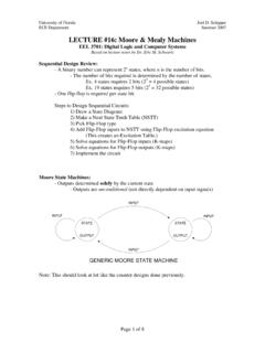
1 Design of the 11011 Sequence Detector A Sequence Detector accepts as input a string of bits: either 0 or 1. Its output goes to 1 when a target Sequence has been detected. There are two basic types: overlap and non-overlap. In an Sequence Detector that allows overlap, the final bits of one Sequence can be the start of another Sequence . 11011 Detector with overlap X 11011011011. Z 00001001001. 11011 Detector with no overlap Z 00001000001. Slide 1 of 23 slides Revised 9/28/2009. Copyright 2009 by Edward L. Bosworth , All rights reserved. Chapter 7 Appendix Design of a 11011 Sequence Detector Problem: Design a 11011 Sequence Detector using JK flip-flops. Allow overlap. Step 1 Derive the State Diagram and State Table for the Problem Step 1a Determine the Number of states We are designing a Sequence Detector for a 5-bit Sequence , so we need 5 states .
2 We label these states A, B, C, D, and E. State A is the initial state. Step 1b Characterize Each State by What has been Input and What is Expected State Has Awaiting A -- 11011 . B 1 1011. C 11 011. D 110 11. E 1101 1. Slide 2 of 23 slides Revised 9/28/2009. Copyright 2009 by Edward L. Bosworth , All rights reserved. Chapter 7 Appendix Design of a 11011 Sequence Detector Step 1c Do the Transitions for the Expected Sequence Here is a partial drawing of the state diagram. It has only the Sequence expected. Note that the diagram returns to state C after a successful detection;. the final 11 are used again. B. 1/0 Note the labeling of the transitions: X /. 1/0. Z. Thus the expected transition from A. A C to B has an input of 1 and an output of 0.
3 1/1 0/0. E D The transition from E to C has an 1/0 output of 1 denoting that the desired Sequence has been detected. The Sequence is 1 1 0 1 1. Slide 3 of 23 slides Revised 9/28/2009. Copyright 2009 by Edward L. Bosworth , All rights reserved. Chapter 7 Appendix Design of a 11011 Sequence Detector Step 1d Insert the Inputs That Break the Sequence The Sequence is 1 1 0 1 1. Each state has two lines out of it one line for a 1 and another line for a 0. The notes below explain how to handle the bits that break the Sequence . Slide 4 of 23 slides Revised 9/28/2009. Copyright 2009 by Edward L. Bosworth , All rights reserved. Chapter 7 Appendix Design of a 11011 Sequence Detector State A in the 11011 Sequence Detector A State A is the initial state.
4 It is waiting on a 1. If it gets a 0, the machine remains in state A and continues to remain there while 0's are input. If it gets a 1, the machine moves to state B, but with output 0. Slide 5 of 23 slides Revised 9/28/2009. Copyright 2009 by Edward L. Bosworth , All rights reserved. Chapter 7 Appendix Design of a 11011 Sequence Detector State B in the 11011 Sequence Detector B If state B gets a 0, the last two bits input were 10 . This does not begin the Sequence , so the machine goes back to state A. and waits on the next 1. If state B gets a 1, the last two bits input were 11 . Go to state C. Slide 6 of 23 slides Revised 9/28/2009. Copyright 2009 by Edward L. Bosworth , All rights reserved. Chapter 7 Appendix Design of a 11011 Sequence Detector State C in the 11011 Sequence Detector C If state C gets a 1, the last three bits input were 111.
5 It can use the last two to be the first two 1's of the Sequence 11011 , so the machine stays in state C awaiting a 0. If state C gets a 0, the last three bits input were 110 . Move to state D. Slide 7 of 23 slides Revised 9/28/2009. Copyright 2009 by Edward L. Bosworth , All rights reserved. Chapter 7 Appendix Design of a 11011 Sequence Detector State D in the 11011 Sequence Detector D If state D gets a 0, the last four bits input were 1100 . These 4 bits are not part of the Sequence , so we start over. If state D gets a 1, the last four bits input were 1101 . Go to state E. Slide 8 of 23 slides Revised 9/28/2009. Copyright 2009 by Edward L. Bosworth , All rights reserved. Chapter 7 Appendix Design of a 11011 Sequence Detector State E in the 11011 Sequence Detector E If state E gets a 0, the last five bits input were 11010.
6 These five bits are not part of the Sequence , so start over. If state E gets a 1, the last five bits input were 11011 , the target Sequence . If overlap is allowed, go to state C and reuse the last two 11 . If overlap is not allowed, go to state A, and start over. Slide 9 of 23 slides Revised 9/28/2009. Copyright 2009 by Edward L. Bosworth , All rights reserved. Chapter 7 Appendix Design of a 11011 Sequence Detector Prefixes and Suffixes: State C. When breaking the input, we look for the largest suffix of the actual input that is an equal length prefix of the desired pattern. State C, with the last input = 1. The last three bits input were 111 . Input Desired Sequence . 111 11011 . 1 bit 1 1 Good match 111 11011 . 2 bit 11 11 Good match 111 11011 .
7 3 bit 111 110 No match. 111 11011 . The last two 1's at this state can form a 2 bit prefix useable at state C. Slide 10 of 23 slides Revised 9/28/2009. Copyright 2009 by Edward L. Bosworth , All rights reserved. Chapter 7 Appendix Design of a 11011 Sequence Detector Prefixes and Suffixes: State E. State E, with last input = 0. The last five bits were 11010 . No suffix of this is a prefix of the target. Input Desired Sequence . 11010 11011 . 1 bit 0 1 No match. 2 bit 10 11 No match. 3 bit 010 110 No match. 4 bit 1010 1101 No match. 5 bit 11010 11011 No match. Slide 11 of 23 slides Revised 9/28/2009. Copyright 2009 by Edward L. Bosworth , All rights reserved. Chapter 7 Appendix Design of a 11011 Sequence Detector Step 1e Generate the State Table with Output Present State Next State / Output X=0 X=1.
8 A A/0 B/0. B A/0 C/0. C D/0 C/0. D A/0 E/0. E A/0 C/1. Step 2 Determine the Number of Flip-Flops Required We have 5 states , so N = 5. We solve the equation 2P-1 < 5 2P by inspection, noting that it is solved by P = 3. So we need three flip-flops. Slide 12 of 23 slides Revised 9/28/2009. Copyright 2009 by Edward L. Bosworth , All rights reserved. Chapter 7 Appendix Design of a 11011 Sequence Detector Step 3 Assign a unique P-bit binary number (state vector) to each state. The simplest way is to make the following assignments A = 000. B = 001. C = 010. D = 011. E = 100. Here is a more interesting assignment. states A and D are given even numbers. states B, C, and E are given odd numbers. The assignment is as follows.
9 A = 000. B = 001. C = 011 states 010, 110, and 111 are not used. D = 100. E = 101. Slide 13 of 23 slides Revised 9/28/2009. Copyright 2009 by Edward L. Bosworth , All rights reserved. Chapter 7 Appendix Design of a 11011 Sequence Detector Step 4 Generate the Transition Table With Output Present State Next State / Output X=0 X=1. Y2Y1Y0 Y2Y1Y0 / Z Y2Y1Y0 / Z. A 0 0 0 0 0 0 / 0 0 0 1 / 0. B 0 0 1 0 0 0 / 0 0 1 1 / 0. C 0 1 1 1 0 0 / 0 0 1 1 / 0. D 1 0 0 0 0 0 / 0 1 0 1 / 0. E 1 0 1 0 0 0 / 0 0 1 1 / 1. Note that bit 0 can clearly be represented by a D flip flop with D0 = X. Slide 14 of 23 slides Revised 9/28/2009. Copyright 2009 by Edward L. Bosworth , All rights reserved. Chapter 7 Appendix Design of a 11011 Sequence Detector Step 4a Generate the Output Table and Equation The output table is generated by copying from the table just completed.
10 Present X= X= The output equation can be obtained from inspection. State 0 1 As is the case with most Sequence detectors , the output Z is 1 for only one combination of present state Y2Y1Y0 0 0. and input. Thus we get Z = X Y2 Y1' Y0. 0 0 0 0 0. This can be simplified by noting that the state 111 does 0 0 1 0 0. not occur, so the answer is Z = X Y2 Y0. 0 1 1 0 0. 1 0 0 0 0. 1 0 1 0 1. Slide 15 of 23 slides Revised 9/28/2009. Copyright 2009 by Edward L. Bosworth , All rights reserved. Chapter 7 Appendix Design of a 11011 Sequence Detector Step 5 Separate the Transition Table into 3 Tables, One for Each Flip-Flop We shall generate a present state / next state table for each of the three flip- flops; labeled Y2, Y1, and Y0.