Transcription of Design of Vacuum Systems for Crude Oil Vacuum …
1 Design of Vacuum Systemsfor Crude Oil Vacuum Tower BIRGENHEIER AND L. WETZEL GRAHAM MANUFACTURING COMPANYBATAVIA, NEW YORKP aper will discuss in detail Design considerations involved inselecting steam ejector/liquid ring pump Vacuum system forcrude tower service. Materials of construction, energy utilization,packaging, system performance and flexibility will be Oil Vacuum Towers require reliable, trouble free vacuumsystems that operate for months on end, between scheduled shut-downs. The key to a well designed system is the utilization ofdependable Vacuum equipment combined to achieve optimumenergy jet ejectors have historically been accepted as being the log-ical and economical means of pulling Vacuum on towers inrefinery service. To produce the high Vacuum required, they arestaged together in two, three, or four stages depending on thelevel of Vacuum .
2 Ejectors can be single element or multi elementsystems ( , twin 50% element, twin 1/3 - 2/3 elements, tripleelement with each 1/ 3 capacity), or triple element with each50% capacity. Multi element Systems allow for flexibility in vary-ing load situations. Along with the ejectors, special designed shelland tube heat exchangers are utilized to condense the steam andhydrocarbons, and in addition cool the gases at the various opti-mum interstage pressures. (Refer to Fig. 1 and 2 for typicalschematics of equipment.) The primary stage(s) vary in size andare generally in the range of 15 to 70 feet long. They are eithermounted on top of the tower pointing vertically down or locatedat the same platform elevation as the intercondensers, which isapproximately 45 feet minimum above the condensate seal potliquid level.
3 Steam jet ejectors have no moving parts and areprobably one of the most trustworthy pieces of equipment thatfunction in a Vacuum system . This does not mean they can beignored indefinitely. Routine inspection, maintenance, and repairis usually taken care of during the normal use medium to high pressure motive steam which passesthrough the motive nozzle where its pressure is dissipated inaccelerating the steam to high velocity as it exits the motive noz-zle mouth. The high velocity jet of steam issued from the nozzlemouth entrains the condensible and non-condensible gases enter-ing the ejector suction from the process (tower). Friction betweenthe motive steam and low pressure gases cause the latter to movewith the motive steam. The steam and gases mix as they passfrom the nozzle mouth into the diffuser.
4 The divergent section ofthe downstream end of the diffuser converts the kinetic energyinto pressure energy by decreasing the velocity of the mixture andincreasing the pressure. A single stage ejector can compress thegases over a range of up to 12 to 1 (depending upon the actualsuction and discharge pressure). (Refer to Fig. 3.)A shell and tube heat exchanger, specifically designed for vacuumservice, is strategically placed between ejector stages to condense alarge portion of condensible gas. Additionally, the non-condensi-ble gases are cooled thus decreasing the load to the next ejectorstage. The condensers utilize cooling tower water and/or riverwater for the condensing Processing Symposium, 19881 Energy costs for the utilities to operate an ejector-condenser unitvaries widely from one part of the country to the with steam, it depends upon the method used to gen-erate (such as coal, oil, gas and electricity).
5 Generally speaking,steam varies from a cost of $ lbs. up to as high as$ lbs. The cost of cooling water varies from as low as$ gallons to as high as $ gallons. For theanalogy that will be used, the cost of cooling water will not beconsidered. A complete, accurate analysis must take into consider-ation the figures that are relevant for the specifIc situation Ring Vacuum Pumps have only been sparingly used in theUnited States in conjunction with steam ejectors for vacuumtower applications in the past. They are a rotating piece of equip-ment that can operate singly, or they can be paralleled to beconsistent with any combination of ejectors. Routine inspection,maintenance and repair is required and is also accomplished dur-ing the normal scheduled turnaround.
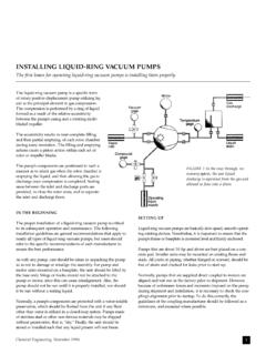
6 As with rotatingequipment, some special consideration has to be given to itemssuch as proper lubrication, vibration due to a faulty motor, poorlydesigned baseplate or pumps not mounted firm and level on thebaseplate. The liquid ring Vacuum pump uses seal liquid (usuallywater) which is thrown to the periphery of the casing and forms aliquid ring. (Refer to Fig. 4.)The liquid ring seals the space between the impeller blades andthe casing. The chambers at the top most part of the impeller hubare filled with liquid. As the impeller rotates, the liquid ringmoves away from the hub, increasing the space in the pumpingchamber. This draws the gas into the chambers. As the impellercontinues to rotate, any gas in the impeller chambers is com-pressed by the liquid ring and expelled through the dischargeport.
7 This sequence is repeated with each revolution. The seal liq-uid absorbs the heat of compression, friction and pump is driven by an electric motor at speeds varying from400 RPM to 1750 RPM. Energy costs for the electricity to oper-ate the motor and for the seal liquid fluid vary quite widely fromone part of the country to the other, the same as with actual electrical costs are generally easy to identify in a cer-tain locality. The cost of the seal liquid (usually water) can almostbe ignored for an energy analysis, since the consumption is verysmall. Also, a complete recirculation type system or partial recir-culation system could be utilized in which the costs are costs vary from $.02/KW-HR to as high as $.10 spiraling increase of fuel costs for generating steam comparedto electrical costs for operating the motors on liquid ring vacuumpumps is the criteria for a positive alternative in energy savings,not to mention the consideration given to the ultimate savings bythe end user for other utility costs (such as cooling tower water),erection costs, and savings resulting in smaller platforms.
8 Theconcept of combining liquid ring pumps with steam jet ejectorsresults in utility cost savings that will have a payoff period from asshort a time as 3 months up to 1-1/2 years. This is entirelydependent upon accurate energy analysis in the locality it isinstalled, materials of construction, quantity of actual non-con-densible gases present, and analyzing the savings in capitalexpenditures of hardware not materials of construction for liquid ring pumps are complete-ly compatible for this service compared to steam ejectors. Thesteam jet ejectors are generally constructed of carbon steel with aHydrocarbon Processing Symposium, 19882stainless steel motive nozzle. There are presently some systemsthat employ all stainless or high nickel alloys. The liquid ringpumps can be supplied in the same or superior performance comparison of a single stage ejector dischargingto atmospheric pressure, versus a single stage liquid ring pump,versus a two stage liquid ring pump is depicted in Figure are several important items to point out in analyzing thecurves.
9 Based upon pumping capacity, a single stage pump shouldbe utilized at pressures of approximately 200 mm HgA and high-er, and a two stage pump at pressures less than 200 mm single stage ejector curve represents the typical performanceoperating in this range. This ejector consumes 432 PPH of 100 PSIG steam while the single stage and two stage pumps absorbapproximately the same BHP of 13. From a hogging or evacua-tion aspect, the time to evacuate 100 cubic feet from atmosphereto 200 mm HgA takes .88 minutes with the ejector and .85 min-utes with the single stage pump, thus, almost the same time; andfurther concluding that the jet and pump are equal in perform-ance for comparison curves shown in Fig. 6 compare the cost of steam and elec-tricity. Observe that rates are listed, since as previously stated thecosts for generating these utilities vary widely from one locality toanother.
10 With these various rates an individual can analyze thecost savings based upon the rates that are applicable. The abcissais labeled in pounds per hour of steam (consumed or saved) . Theordinate is the steam or electrical cost per year. Example:Designing a three stage ejector system in which the third stageHydrocarbon Processing Symposium, 19883ejector consumes 1830 pounds per hour of 100 PSIG steam andit is desired to compare the cost savings by using a combinationsystem, thus ending up with a two stage ejector and a liquid ringvacuum pump of comparable capacity. The single stage liquidring pump absorbs 50 BHP and is of equal performance to thethird stage ejector. Arbitrarily selecting a steam cost of $ per1000 pounds and an electrical cost of $.07 per KW-HR, thesteam cost per year to operate the third stage ejector is found bytaking the 1830 pounds per hour of steam consumed and movevertically upward until the curve labeled $ per 1000 poundsis intersected.