Transcription of DESIGN, OPERATION, AND MAINTENANCE …
1 DESIGNDESIGN, OPERATION, AND MAINTENANCE CONSIDERATIONS FOR IMPROVED DRY GAS SEAL RELIABILITY IN CENTRIFUGAL COMPRESSORSJohn S. StahleyDresser-Rand, Olean, NY, USAA bstractThe use of dry gas seals in process gas centrifugal compressors has increased dramatically over the last twenty years, replacing traditional oil film seals in most applications. Over 80% of centrifugal gas compressors manufactured today are equipped with dry gas seals. As dry gas seals have gained acceptance with users and centrifugal compressor original equipment manufacturers (OEMs), the operating envelope is continually being greater demands are being placed on dry gas seals and their support systems, requiring continual improvements in the design of the dry gas seal environment, both internal and external to the compressor is a leading cause of dry gas seal degradation and reduced reliability.
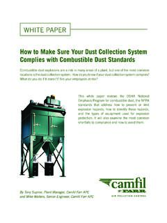
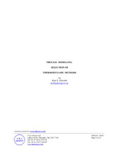
2 This paper will examine the experiences of one centrifugal compressor OEM in this regard. Several potential sources of dry gas seal contamination will be analyzed, drawing from actual field experience, and various means of increasing dry gas seal reliability will be compressors in process gas service require shaft sealing to prevent the process gas from escaping the compressor case uncontrolled, into the atmosphere. Multi-stage, "beam" style compressors require two seals, one at each end of the shaft (Fig. 1). Single stage, "overhung" style compressors require a single shaft seal, directly behind the impeller. Dry gas seals can be applied to accomplish the required shaft :///F|/USERS/mafisher/MYDOCS/ (1 of 15) [01/21/2003 1:22:42 PM]DESIGNF igure 1 - Location of Shaft SealsDry Gas SealsDry gas seals are available in a variety of configurations, but the "tandem" style seal is typically applied in process gas service (Fig.)
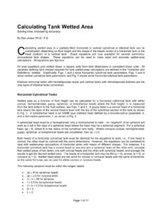
3 2). Tandem seals consist of a primary seal and a secondary seal, contained within a single cartridge. During normal operation, the primary seal absorbs the total pressure drop to a vent system, and the secondary seal acts as a backup should the primary seal :///F|/USERS/mafisher/MYDOCS/ (2 of 15) [01/21/2003 1:22:42 PM]DESIGNF igure 2 - Typical Tandem Gas Seal / Barrier Seal ConfigurationDry gas seals are basically mechanical face seals, consisting of a mating (rotating) ring and a primary (stationary) ring (Fig. 3). During operation, grooves in the mating ring (Fig. 4) generate a fluid-dynamic force causing the primary ring to separate from the mating ring creating a "running gap" between the two rings. A sealing gas is injected into the seal, providing the working fluid for the running gap and the seal between the atmosphere or flare system and the compressor internal process gas.
4 For a more complete description of dry gas seal principles of operation, see Shah (1988).Inboard of the dry gas seal is an inner labyrinth seal, which separates the process gas from the gas seal. Outboard of the dry gas seal is a barrier seal, which separates the gas seal from the compressor shaft bearings (Fig. 2).file:///F|/USERS/mafisher/MYDOCS/ (3 of 15) [01/21/2003 1:22:42 PM]DESIGNF igure 3 - Gas Seal Components file:///F|/USERS/mafisher/MYDOCS/ (4 of 15) [01/21/2003 1:22:42 PM]DESIGNF igure 4 - Grooves in Seal Mating RingDry Gas Seal SystemsThe use of dry gas seals requires a system designed to supply sealing gas to the seal as a sealing and working fluid for the running gap. These gas seal systems are normally supplied by the compressor OEM mounted adjacent to the compressor.
5 There are two basic types of gas seal systems - differential pressure (D P) control and flow control. D P systems (Fig. 5) control the supply of seal gas to the seal by regulating the seal gas pressure to a predetermined value (typically 10 PSI) above a reference (sealing) pressure. This is accomplished through the use of a differential pressure control control systems (Fig. 6) control the supply of seal gas to the seal by regulating the seal gas flow through an orifice upstream of the seal. This can be accomplished with a simple needle valve, or through the use of a differential pressure control valve monitoring pressures on either side of the D P systems basically control the flow of seal gas through a labyrinth seal, this can sometimes result in high seal gas flows through the inner seal labyrinth.
6 Variations in the inner seal labyrinth clearance can result in high variations of seal gas flow. The majority of the seal gas flows across the inner seal labyrinth and back into the compressor, and very little flow is actually required for the gas seal. This "recycled" flow is inefficient, and uses more energy. This situation becomes more critical in high pressure applications due to the higher mass flows of gas involved. Since flow control systems control the flow of seal gas through an orifice, the flow rate is constant and does not vary with labyrinth clearance. Flow can control systems can be applied when reduced seal gas flows are :///F|/USERS/mafisher/MYDOCS/ (5 of 15) [01/21/2003 1:22:42 PM] design Figure 5 - Differential Pressure Control SystemFigure 6 - Flow Control Systemfile:///F|/USERS/mafisher/MYDOCS/ (6 of 15) [01/21/2003 1:22:42 PM] design GAS SEAL ContaminationThe running gap between the primary and mating gas seal rings is typically around 3 to 4 microns, about 1/20th the diameter of a human hair.
7 Ingress of foreign material (solid or liquid) into this very narrow seal running gap can cause degradation of seal performance (excessive gas leakage to the vent) and eventual failure of the seal. Foreign material within the running gap of the seal results in increased shearing forces between the primary and mating rings. The seal components then overheat, leading to some form of mechanical seal failure such as o-ring deterioration, mating ring cracking, etc.).There are three primary sources of gas seal contamination:l Process gas (from the inboard or high-pressure side of the seal) l Bearing lubrication oil (from the outboard or low-pressure side of the seal) l Seal gas supply itself (injected into the seal) Contamination from Process GasContamination from process gas can occur when there is insufficient sealing gas pressure to overcome the reference pressure, allowing process gas to come into direct contact with the seal ring faces.
8 Contaminants existing within the process gas can then damage the from Bearing Lubrication OilA barrier seal is required on the outboard side of the dry gas seal, between the gas seal and the compressor bearing housing area (Fig. 2). This seal is typically buffered with air or nitrogen. The primary function of the barrier seal is to prohibit the flow of bearing lubrication oil or oil mist into the gas seal. Contamination of the dry gas seal from lube oil can occur when the barrier seal fails to function as from Seal Gas SupplyContamination from the seal gas supply occurs when the sealing gas is not properly treated upstream of the dry gas seal. Gas seal manufacturers have stringent requirements for seal gas quality. Typically, the sealing gas must be dry and filtered of particles 3 micron (absolute) and larger.
9 Filters are normally provided in the gas seal system to address this requirement. While typical systems are supplied with coalescing-type filters, such devices may be inadequate depending on the source of seal gas to improve gas seal reliabilityAll three types of contamination described previously are influenced by the approach taken in the design of the gas seal environment, the availability of seal gas sources of supply to cover all operating conditions, and the operation and MAINTENANCE of the compressor or gas seal system. There are various design , operational, and MAINTENANCE techniques that can be applied to mitigate gas seal contamination and increase gas seal reliability / design ConsiderationsVarious features of a compressor's design have an impact on gas seal performance and reliability.
10 Of particular concern is the contamination of the dry gas seal with bearing lubrication :///F|/USERS/mafisher/MYDOCS/ (7 of 15) [01/21/2003 1:22:42 PM]DESIGNThe design of the bearing and seal cavities should consider prevention of lube oil migration into the gas seals. Lube oil will have a natural tendency to migrate along the shaft from the bearing to the barrier seal, requiring the bearing cavity to be designed to minimize the exposure of the barrier seal to lube oil. Flooded bearing drains place greater demands on barrier seals, so it is also imperative to size and locate bearing cavity drain porting and piping to allow for the maximum rate of drainage of lube oil from the cavity. To facilitate drainage of the oil from the shaft, adequate axial shaft spacing and/or oil "slingers" between the bearing and the barrier seal should be considered.