Transcription of Designing a UCD3138 Controlled Single Phase PFC - TI.com
1 Application Report SLUA708 March, 2014 1 Designing a UCD3138 Controlled Single Phase PFC Bosheng Sun High Performance Isolated ABSTRACT The UCD3138 [1] is a digital power supply controller from Texas Instruments offering superior levels of integration and performance in a Single chip solution. The flexible nature of the UCD3138 makes it suitable for a wide variety of power conversion applications. In addition, multiple peripherals inside the device have been specifically optimized to enhance the performance of ac/dc applications such as power factor correction (PFC). The UCD3138 is a fully programmable solution offering customers complete control of their application.
2 However, the use of digital controllers in PFC design brings new challenges to many analog designers in their effort to change the design from the analog space to its new digital environment. This application note gives a step by step guidance on how to design a UCD3138 Controlled Single Phase PFC. It covers the hardware interface, voltage loop and current loop implementation, system protection, firmware structure, internal state machines, as well as some advanced features. Finally, a graphical user interface (GUI) and a guidance for tuning the coefficients of a PFC system are presented.
3 For interleaved or bridgeless PFC design, please refer to application notes [2] and [3]. Contents 1 Overview .. 3 Block Diagram .. 3 Signal Conditioning and Interface .. 4 2 Voltage Loop .. 4 Overview .. 4 Firmware Implementation of PI Controller .. 4 3 Current Loop .. 5 Overview .. 5 Multiplier Gain Km .. 6 Vin Sensing and Rectification .. 6 Calculate Vin_rms2 .. 7 Calculate Vin Feed Forward .. 8 Calculate Current Reference .. 8 Current Feed Back Front End Configuration .. 9 Current Loop Filter Configuration .. 9 DPWM Configuration .. 11 4 System Protection .. 12 Software OVP Protection .. 12 Hardware OVP Protection.
4 13 Cycle by Cycle Current Protection .. 13 5 Advanced Features .. 13 Frequency Dithering .. 13 AC Drop Detection .. 14 PFC ZVS or Valley Switching Control .. 16 SLUA708 March 2014 2 Designing a UCD3138 Controlled Single Phase PFC X-CAP Reactive Current Compensation .. 16 input Power and RMS Current Measurement .. 17 A Novel Burst Mode AC Cycle Skipping .. 17 Harmonic Injection .. 17 Duty Ratio Feedforward Control .. 18 6 Firmware structure .. 18 Background Loop .. 19 Standard Interrupt Loop (IRQ) .. 20 Tasks Distribution State Machine .. 20 PFC State Machine .. 21 Fast Interrupt (FIQ) .. 23 7 Graphical User Interface (GUI).
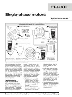
5 23 8 PFC Tuning and THD Reduction .. 25 Reference: .. 25 Figures Figure 1. UCD3138 Controlled Single Phase PFC block diagram .. 3 Figure 2. Current loop .. 6 Figure 3. AC Drop Detection .. 15 Figure 4. A New ZVS/Valley Switching Control Algorithm.. 16 Figure 5. Firmware Structure .. 18 Figure 6. PFC State Machine .. 22 Figure 7. Monitor PFC Operating Status .. 24 Figure 8. Configure PFC Operation Setpoints .. 24 Figure 9. Tune PFC Control Loop .. 25 SLUA708 March 2014 Designing a UCD3138 Controlled Single Phase PFC 3 1 Overview Block Diagram Vs Fusion Power PeripheralAD_03 RLVbusQ1D1 CbCOMP_DSignalConditioningRs1 EMI Filter & InrushRelayGateDriverL1 IinD3AD_07 DPWM1 SignalConditioningSignalConditioningVinI q1PI(Gv)++-- UCD3138 VrefVbEvIinCLA1(Gc)CalculateVrmsCalculat e1/Vrms2 IrefABc+UiVrmsConditioning&Rectification KmSignalConditioningFE0I_CT1 DPWM1 BDPWM1 BVin_lVbus_senVbus_senVin_nI_CT1 Iin_senseEAP0 UARTI nterfaceVin_lAD_08 Cycle by cycle limitVin_nVbus_ovCOMP_FOVPVbus_ovPMBusIn terfaceIin_fdbkIin_fdbkAD_02 Iin_sense Figure 1.
6 UCD3138 Controlled Single Phase PFC block diagram Figure 1 is an example of block diagram of a Single Phase PFC Controlled by the UCD3138 . The input voltage Vin is sensed before the bridge rectifier, the line and neutral are sensed separately by two ADC channels AD_07 SLUA708 March 2014 4 Designing a UCD3138 Controlled Single Phase PFC and AD_08. PFC output voltage Vbus_sen is sensed by another ADC channel AD_03. In addition, a separate Vout sensing circuit is connected to an on chip analog comparator COMP_F for over voltage protection (OVP). The current signal is sensed by current shunt and its feedback signal Iin_fdbk is connected to error ADC channel EAP0 for current loop control.
7 This signal is further filtered and connected to AD_02 for input power and RMS current measurement. A current transformer is used to sense the MOSFET instantaneous current and its output is connected to an on chip analog comparator, COMP_D, for cycle-by-cycle current protection. The control loop generates one PWM output, DPWM1B, to drive the MOSFETs through an external gate driver. Average current mode control is used for input current regulation. The current reference is calculated based on Vin, voltage loop output and input voltage feed forward. The averaged input current signal is sensed and compared with this reference, the error goes through a 2-pole 2-zero digital compensator CLA1; a PWM signal is generated based on the compensator output to control the PFC.
8 It needs to be mentioned here that the above configuration reflects TI s PFC evaluation board PWR026. It is not necessary to follow this configuration. For example, Iin_fdbk can be connected to a different EAP channel, a different CLA can be used for compensation, and the PFC can be driven by different DPWM outputs as well. However, in order to maximize source code reuse and reduce design time it is recommended to use a configuration similar to PWR026. Signal Conditioning and Interface For each input signal to the UCD3138 , its magnitude should accommodate the measurement range of the UCD3138 .
9 In the UCD3138 , the ADC measurement range is 0 , the error ADC measurement range is 0 - , the analog comparator range is 0 On the other hand, to have the best signal-to-noise ratio, the input signal should be as big as possible. For these reason, the signal conditioning for each input signal should follow the subsequent guidelines. For Vin, the voltage divider:max_* For Vout, the voltage For I_shunt, the OP_AMP gain: shuntiniRIK* For current transformer: I_CT1 2 Voltage Loop Overview Since the speed constraints on the voltage loop bandwidth are typically low, it can easily be implemented by pure firmware.
10 As shown in Figure 1. Vout_sen is sensed by a 12-bit ADC. An error signal is calculated based on the target output voltage and then processed by a proportional-integral (PI) controller. The output of this PI controller will take part in the current reference calculation. To meet the load transient response requirement, a non-linear PI gain is used. When the voltage error exceeds a threshold, a larger PI gain is used. Firmware Implementation of PI Controller Following is the code example for this nonlinear PI controller. Two different gains are used in this example. If the load transient response still is not met, a third or forth gain can be added.