Transcription of Designing and Drawing a Sprocket - Gears EdS
1 105 Webster St. Hanover Massachusetts 02339 Tel. 781 878 1512 Fax 781 878 6708. Designing and Drawing a Sprocket Visualizing ideas through the creation of CAD solid models is a key engineering skill. The following text offers the information and procedural steps necessary to engineer a CAD. profile of the #25 pitch, 30 tooth Sprocket found in the Gears -IDS kit of parts. This process provides a method for generating solid models of any standard Sprocket , pitch, number of teeth, or configuration. This exercise also provides students and instructors with an excellent way to incorporate 8th and 9th grade algebra and geometry knowledge with engineering Drawing skills to produce the design elements necessary to fully visualize their mechanical creations.
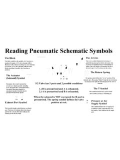
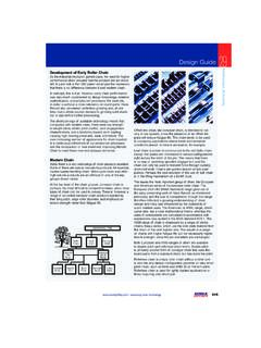
2 <B. Fig. 1 Sprocket Tooth Geometry (Adapted from the American chain Association Chains for Power Transmission and Material Handling handbook. Gears Educational Systems 105 Webster St. Hanover Massachusetts 02339 Tel. 781 878 1512 Fax 781 878 6708 1. Sprocket Tooth Design Formulas Refer to Fig. 1 Sprocket Tooth Geometry The tooth form of a Sprocket is derived from the geometric path described by the chain roller as it moves through the pitch line, and pitch circle for a given Sprocket and chain pitch. The shape of the tooth form is mathematically related to the chain Pitch (P), the Number of Teeth on the Sprocket (N), and the Diameter of the Roller (Dr).)
3 The formulas for the seating curve, radius R and the topping curve radius F. include the clearances necessary to allow smooth engagement between the chain rollers and Sprocket teeth. The following formulas are taken from the American chain Association Chains for Power Transmission and Material Handling handbook, and they represent the industry standards for the development of Sprocket tooth forms. P = chain Pitch 64 56 . yz = Dr sin(17 ) sin(18 ). N . N = Number of Teeth Dr = Roller Diameter ( See Table) N. Ds = (Seating curve diameter) = Dr + ab = Dr 180 . W = Dr cos R = Ds/2 = Dr + N. 60 . A = 35 +. N 180.
4 V = Dr sin 56 N. B = 18 . N. 56 64 . F = Dr cos(18 ) + cos(17 .. ) .0015. ac = x Dr N N . 60 . M = x Dr cos( 35 + ) H= F 2 ( Dr . P 2. ). N 2. 60 . T = x Dr sin ( 35 + ) P 180 180 . N S= cos + H sin E = Dr + 2 N N. Chordal Length of Arc xy = ( Dr + ) P. PD =. 28 180 . sin ( 9 ) sin . N N . Table 1. Gears Educational Systems 105 Webster St. Hanover Massachusetts 02339 Tel. 781 878 1512 Fax 781 878 6708 2. Procedure for Drawing a Sprocket In this example we will draw the tooth form for the Gears -IDS 30 tooth Sprocket . Refer to , the Sprocket Formulas and the Maximum Roller Diameter Table. NOTE: This is primarily an algebra and geometry exercise.
5 When Drawing a Sprocket model for the first time there will likely be problems with arcs that are not exactly tangent to lines, or line lengths that are not exact to 3 or 4 decimal places. This can cause problems if you are using modeling software. Use your Drawing tools and common sense in order to create tangent relationships and working line lengths. With experience, it is possible to draw extremely accurate Sprocket models by using the associated spreadsheet and following the directions below. chain Number Pitch Max Roller Diameter 25 *. 35 3/8 *. 41 40 5/16. * This refers to the bushing diameter since the chain pitch is small and roller-less.
6 1.) Determine the values for P, N and Dr for a 30T Sprocket 2.) Calculate the remaining values using the formulas on the preceding page. Enter the data in the table below. Note: this can be accomplished with a calculator or by using the Gears -IDS spreadsheet ( ). P = (For the example Sprocket ) A= W=. B= V=. N = 30 (For the example Sprocket ). ac = F=. Dr = (See table above). M= H=. Ds = T= S=. R= E= PD =. Yz =. ab =. Gears Educational Systems 105 Webster St. Hanover Massachusetts 02339 Tel. 781 878 1512 Fax 781 878 6708 3. Pitch Circle 3.) Draw the Pitch Circle using a radius equal to PD. ( Radius = for this example).
7 Note: In order to obtain the best results, it will be necessary to fully constrain all the entities. Often it is helpful to fix the entities or geometry as they are created. Specify dimension values to 4 decimal places. 4.) Draw a construction line ( 1, 2 ) from the center of the circle through the top quadrant. Where this line intersects the circle is the location of point a. 1. 5.) Draw a horizontal line ( 3, 4 ) through point a, 3 4 (the top quadrant,) of the pitch circle. Make this line tangent to the pitch circle. 2. 1. Circle Radius 4. 3. 6.) Draw a circle with radius = R. at the intersection of lines 1,2 Circle and 3,4.
8 Diameter Radius = R from calculations or spreadsheet = . 2. Gears Educational Systems 105 Webster St. Hanover Massachusetts 02339 Tel. 781 878 1512 Fax 781 878 6708 4. 1. 7.) Offset lines 1,2 and 3,4. distances M and T..0831 M respectively. These lines .0626 will intersect at point c Note: Throughout this exercise it is c important to continually save your work and to continually verify the T accuracy of every dimension. 4. 3. 2. 8.) Draw line cx at angle A. Line cx must extend beyond the c circle. y Angle A. Angle B. 9.) Draw line cy. Line x cy = length E. ( E = .1708 for this example). and is drawn at an angle B from cx.
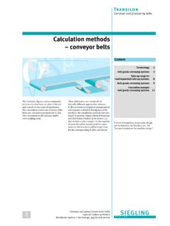
9 Gears Educational Systems 105 Webster St. Hanover Massachusetts 02339 Tel. 781 878 1512 Fax 781 878 6708 5..0831 10.) Draw arc xy (Shown in blue ). with radius E. ( E = .1708 for this example). Use the 3 point arc command to set the arc from cy = Length E. point x to point y. After Drawing the arc dimension c the radius to length E). Note: The center of arc xy appears to be at or near point c. Do not make the assumption that this is y always the case. With sprockets of differing numbers of teeth, the center of arc xy will likely NOT be at point c. x Arc xy has a radius = to length E..0831. The image on the right illustrates the arc dimension for the 30 tooth #25 pitch Sprocket used in this example.
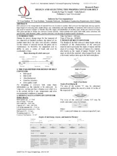
10 Gears Educational Systems 105 Webster St. Hanover Massachusetts 02339 Tel. 781 878 1512 Fax 781 878 6708 6. 11.) Draw line segment .0831 yz (Shown in green). perpendicular to z line cy. This can be drawn initially to any point on c line cy. After Drawing the line segment yz 900 perpendicular to cy, move the lower y end of the line segment to point y as shown below..0831 In the example on the left, line yz (shown in green) has been moved z to the endpoint of line cy (point y ). It remains perpendicular to line cy. c Constrain this line by fixing it in position. Line zy is fully y constrained when it appears in black.