Transcription of Designing Concrete Structures
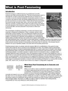
1 American Concrete Institute Advancing Concrete knowledgeDesigning Concrete Concrete Basement Wall DesignACI E702 Example Problems Buried Concrete Basement Wall L. H. Taber, PE Page 1 of 9 Example Problem: Buried Concrete Basement Wall Design Problem Statement Provide a detailed strength design (durability and other considerations not included) for a new buried Concrete basement wall in a single-story masonry building using the given information. Given Information See Figure 1 for general layout and dimensions of wall section.
2 Designer s Assumptions Design wall with fixed base and pinned top (propped cantilever) Neglect corner regions (wall spans one-way only) Top slab is in place and has achieved full strength prior to backfilling (no construction case considered in example) Use center-to-center of supports dimension of 15 feet for both moment and shear calculations (simplification, will be conservative for shear calculations) No vehicular traffic around building No eccentricities associated with vertical load (simplification for example purposes only) Given Information Additional Guidance Applicable Design Code is ACI 318-11 referenced by major building codes (IBC, etc) Concrete compressive strength, fc = 4,000 psi common industry value; see project guidelines Reinforcement yield strength, fy = 60,000 psi common industry value; ASTM A615, Grade 60 Soil equivalent fluid pressure = 60 psf/ft obtain from geotech report.
3 Varies widely Use 2 ft additional soil surcharge to account for compaction pressure common technique for short walls and vehicle loading; other techniques exist for deeper walls Ground water table is deep below structure no buoyancy concerns; simplifies soil loading structure in a low seismic region seismic forces do not control design Top slab acts as diaphragm pinned top support for wall Total service-level vertical dead load on wall = kips/ft (including slab self-weight) reasonable value for example purposes; determine load path and sum loads to get value Total service-level vertical live load on wall = kips/ft reasonable value for example purposes; determine load path and sum loads to get value Discussion: In practice, a designer would also need to consider a partially fixed and/or pinned base.
4 Realistically, the base support acts somewhere between fully fixed and fully pinned depending on the soil, relative wall/slab thicknesses and reinf detailing. A design check would also be needed at the building corners where the wall will attempt to span both vertically and horizontally.(sketch not to scale) 14 -0 10 1 -2 12 CMUF igure 1 Version ; Updated April 2013 ACI E702 Example Problems Buried Concrete Basement Wall Page 2 of 9 Calculations ReferencesLoad Determination Soil Pressure: Max soil pressure, qmax, at base = (60 psf/ft)(15 ft + 2 ft) = 1020 psf = ksf Min soil pressure, qmin, at top = (60 psf/ft)(2 ft) = 120 psf = ksf Service-Level Shear and Moment from Soil Pressure at base of wall: From third-party software.
5 Vsoil,max = k/ft Msoil,max = k-ft/ft Factored Shear and Moment from Soil Pressure at base of wall: Using Eq. 9-2 with added per Section (a). Dead, live, roof, snow & rain loads have zero lateral component in this example. Shear: Vu = ( k/ft) = k/ft Moment: Mu = ( k-ft/ft) = k-ft/ft Factored Vertical Axial Force from building, elevated slab above and self-weight: For example purposes only, assume total live load given accounts for roof, snow, rain, etc. A one foot thick wall is initially assumed here, verify later in calculation.
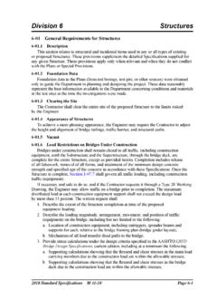
6 Total service dead load: k/ft + (14 ft)(1 ft)( kcf) = k/ft Axial: Pu = ( k/ft) + ( k/ft) = k/ft Note: by inspection, the other load combinations in Section do not : In practice, a designer would need to check both the positive and negative moments and shears in the wall for all load combinations. A designer can optimize the amount of reinforcement at individual locations ( inside face vs outside face). To limit constructability concerns and associated cost impacts, a designer should limit the use of multiple reinforcement sizes or spacing callouts.
7 KsfFigure 2 k-ft/ft k-ft/ft Moment (Msoil) Figure 4 Shear (Vsoil) Figure 3 k/ft k/ft Sec ; Sec ; Eq 9-2 w/ added NOTE: All references are for ACI 318-11 (UNO) ACI E702 Example Problems Buried Concrete Basement Wall Page 3 of 9 Calculations ReferencesOverview of ACI 318 Chapter 14 (Walls) Requirements Design shall satisfy Sections and , plus , or o Section described the general requirements o Section provides minimum reinforcement requirements o Sections , and provide three different design methods (only one of which is used for any given design) Shear design shall be in accordance with Section (Provisions for walls).
8 Minimum reinforcement requirements are: o Vertical reinf assume of horizontal gross Concrete area (assumption is valid if bar size is #6 or larger, conservative if not) o Horizontal reinf assume of vertical gross Concrete area (assumption is valid if bar size is #6 or larger, conservative if not) o Vertical shear reinf larger of Equation 11-30 and of horizontal gross Concrete area o Horizontal shear reinf of vertical gross Concrete area Use a maximum spacing of 18 inches (valid for walls thicker than 6 inches and longer than 7 -6 )
9 Section (Empirical design method) is not considered appropriate for this example due to the higher lateral load and potential for the load resultant to have an eccentricity greater than h/6. A more appropriate example for this method can be found in PCA Notes, see the Additional Reading section below. Section (Alternative design of slender walls) is not applicable for this example due to the fixed base assumption. An example using this method can be found in PCA Notes, see the Additional Reading section below. Section (Walls designed as compression members) appears to be the most appropriate method for this example.
10 This method uses the flexure and axial requirements in Chapter 10 ( , , , and ) and Chapter 14 ( and ). Shear Design Assume a 12 inch thick wall Concrete shear strength: for a longer wall, approaches (conservative) is for normal weight Concrete (Sec ) using a unit length approach, so b0 = 12 in/ft assume d = inches based on #8 bar and 2 inches of cover (conservative for smaller bars) Note: this equation now matches Eq. 11-3 in Section , which is the basic shear equation for non- prestressed members. Sec Sec Sec ; ; ; ; Eq 11-30 dbf 42V0'CC Sec ; ; Eq 11-31 k/ft ( )VC Sec.