Transcription of Designing Fillet Welds for Skewed T-joints—Part 1
1 Welding Innovation Vol. XIX, No. 1, 20027 Designing Fillet Welds for Skewed T-joints part 1 Practical Ideas for the Design Professional by Duane K. Miller, , FileIntroductionDetailing Fillet Welds for 90-degree T-joints is a fairlystraightforward activity. Take the 90-degree T- joint and skewit that is, rotate the upright member so as to create anacute and obtuse orientation, and the resultant geometryof the Fillet Welds becomes more complicated (see Figure1). The greater the degree of rotation, the greater the differ-ence as compared to the 90-degree series of equations can be used to determine weld sizesfor various angular orientations and required throat dimen-sions. Since the weld sizes on either side of the joint arenot necessarily required to be of the same size, there are avariety of combinations that can be used to transfer theloads across the joint .
2 While there are theoretical savingsto be seen by optimizing the combinations of weld sizes,rarely do such efforts result in a change in Fillet weld size ofeven one standard prescribe different methods of indicating therequired weld size. These are summarized acute angles become smaller, the difficulty ofachieving a quality weld in the root increases. The Structural Welding Codedeals with this issue byrequiring the consideration of a Z-loss edition of Design File addresses the situation wherethe end of the upright member in the Skewed T- joint is par-allel to the surface of the other member. A future DesignFile column will consider the situation in which the uprightmember has a square cut on the end, resulting in a gap onthe obtuse side. Also to be addressed in the future areweld options other than Fillet Welds in Skewed GeometryFigure 1 provides a visual representation of the issue.
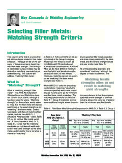
3 Forthe 90-degree orientation, the weld throat is of theweld leg dimension. This relationship does not hold true forfillet Welds in Skewed joints. On the obtuse side, the weldthroat is smaller than what would be expected for a filletweld of a similar leg size in a 90-degree joint , and theopposite is the case for the acute side. These factors mustbe considered when the Fillet weld leg size is determinedand examination of the Fillet Welds on the Skewed jointraises this question: What is the size of the Fillet weld in askewed joint ?Figure 1 illustrates the Fillet weld leg size for a Skewed T- joint , and is designated by . This, however, is inconsis-tent with AWS Terms and Definitions(AWS ) whichdefines a Fillet weld leg as The distance from the jointroot to the toe of the Fillet weld .
4 According to this definition,and as shown in Figure 1, the Fillet weld leg is dimension b. The dimension that is labeled is the distance from amember to a parallel line extended from the bottom weldf1f2 LEGSIZELEGSIZEDIHEDRAL ANGLE135 MAX0 DIHEDRALANGLE60 MIN0b1b2b2b1t1t2 1 2 1 2 2 1 Figure 1. Equal throat sizes (t1= t2).8 Welding Innovation Vol. XIX, No. 1, 2002toe. While not technically correct according to AWS , itis the dimension and terminology used when Fillet Welds inskewed joints are discussed in the AWS StructuralWelding Code, as well as other AWS publications ( , TheWelding Handbook, ninth edition, volume 1). Such termi-nology will be used raises an additional question: What would a weldinspector actually measure when dealing with a Fillet weldin a Skewed T- joint ?
5 Conventional Fillet weld gauges couldbe used to measure the obtuse side s Fillet weld leg dimen-sion as shown in Figure 1. Dimension b would be diffi-cult to measure directly since the location of the weld rootcannot be easily determined. Welds on the acute side areimpossible to measure using conventional Fillet weldgauges. The face dimension f, however, offers an easyalternative: when this dimension is known for the weld sizeand the dihedral angle, the welder and inspector can easilydetermine what the actual size is by using a pair ofdividers. Alternately, a series of simple gauges of variouswidths could be made to directly compare the requirementsto the actual weld size. Thus, dimension f may be impor-tant for controlling weld sizes in Skewed sizing a Fillet weld for 90-degree T-joints or Skewed T-joints, the starting point is to determine the required throatsize needed to resist the applied loads.
6 From the throatdimension, the Fillet weld leg size can be determined. Threeoptions will be considered:Where the throat size is the same on either side of thejoint (see Figure 1)To determine the required Fillet weld size for a given throat,the following relationship can be used:The width of the face of the weld ( f ) can be found fromthis equation:Dimension b, that is, the true Fillet leg size, can be foundfrom this relationship:Finally, the cross-sectional area of the weld metal can bedetermined from the following:Where the leg size is the same on both sides (see Figure 2)If the designer decides to make both Welds with the sameleg size (as is illustrated in figure 2), the first required stepis to determine the composite total dimension of the twothroat sizes. This dimension tT is then inserted into the fol-lowing equations to determine the two throats t1 and t2.
7 Equations 1 4 can be used to find the corresponding filletweld leg size, face dimension, b dimension, and cross-sectional area. These calculations will be made using theapplicable throat dimension t determined from equations5 and 6, not the total throat dimension tT used in equa-tions 5 and a minimum quantity of weld metal is used (see Figure 3)Even a casual review of Figure 1 shows that, when filletweld leg sizes are specified to be of the same size oneither side of the Skewed T- joint , the use of weld metal isas efficient as could be. Minimum weld metal can beobtained by taking advantage of the more favorable condi-tion that results on the acute side where a greater weldthroat can be obtained for the same quantity of metal thatwould be placed on the obtuse minimize the volume of weld metal used in the combina-tion of the two Welds , the following equations may be usedonce the total throat dimension tT is known: = 2 t sin ( ) 2f = 2 t tan ( ) 2cos ( )b = 2tA = t2 tan ( ) 2bbbbt1t2 2 1 Figure 2.
8 Equal Fillet weld leg sizes ( 1= 2).t1 = tTcos ( ) 21cos ( ) 21+ cos ( ) 22t2 = tTcos ( ) 22cos ( ) 21+ cos ( ) 22t1 =1 + tan2 ( ) 21tTt2 =1 + tan2 ( ) 22tT(1)(5)(6)(7)(8)(2)(3)(4)Welding Innovation Vol. XIX, No. 1, 20029 Although the preceding calculations are not particularly dif-ficult, Table 1 has been provided to simplify the A and B are used to determine Fillet weld legsizes and face widths for various dihedral angles. To obtainthe required Fillet weld size, the calculated throat is multi-plied by the factor in Column A. Face widths can be foundfollowing the same the same leg size is desired on either side of the joint ,columns C-E are used. In this case the total weld throat tT is used, as opposed to what was done with columns A and the minimum weld volume, columns F H can be , the total weld throat tT is will be discussed below, for dihedral angles of 30 60degrees, the Code requries the application of a Z-lossfactor.
9 Thus, the values in Table 1 that apply to dihedral angleswhere this applies are shown in blue numbers to remind theuser to incorporate this factor into the weld throat of Dihedral AngleAWS Structural Welding Code Steelprovides for fivegroupings of Skewed T-joints, depending on the range ofsizes of the dihedral angle: a) Obtuse angles greater than100 degrees, b) angles of 80 100 degrees, c) acute anglesof 60 80 degrees, d) acute angles of 30 60 degrees, ande) acute angles of less than 30 degrees. Each is dealt within a slightly different manner. ABC DEFGHphi1 degleg sizeface widththroatleg size face widththroatleg size face 3. Minimum weld & Face DimensionsMultipy by tSame Leg SizeMultipy by tTMinimum weld VolumeMultipy by tTDihedral AngleTable numbers indicate that Z-loss factors must be angles greater than 100 degreesFor this category, contract drawings should show therequired effective throat.
10 Shop drawings are to show therequired leg dimension, calculated with equation 1, or byusing columns C or D of Table 1 (AWS , , ).Angles of 80 100 degreesFor this group, shop drawings are required to show the Fillet leg size (AWS , para ). While notspecifically stated in the code, the assumption is that contract drawings also show this of 60 80 degreesFor this category, contract drawings should show therequired effective throat. Shop drawings are to show therequired leg dimension (AWS , para , )Angles of 30 60 degreesContract drawings are to show the effective throat. Shopdrawings are required to show the required leg dimensionsto satisfy the required effective throat, increased by the Z-loss allowance .. (AWS , para , ).The Z-loss factor is used to account for the likely incidenceof poor quality welding in the root of a joint with a smallincluded angle.