Transcription of Designing for a Low Resistance Earth Interface …
1 Designing For A Low Resistance Earth Interface (Grounding) Roy B. Carpenter, Jr. Joseph A. Lanzoni An LEC Publication Revised 2007 Designing for a Low Resistance Earth Interface -Rev. B-102407 Designing FOR A LOW Resistance Earth Interface (GROUNDING) Roy B. Carpenter, Jr. Joseph A. Lanzoni October 2007 Introduction Grounding (or earthing) is the art of making an electrical connection to the Earth . The process is a combination of science and art as opposed to pure science, because it is necessary to test the options, as opposed to using predetermined methods and calculations.
2 The options for each site must be determined through visualization and evaluation, individually, using a related analytical process. The Earth must be treated as a semiconductor, while the grounding electrode itself is a pure conductor. These factors make the design of an earthing system complex, not derived from a simple calculation or the random driving of a few rods into the soil . Knowledge of the local soil conditions is mandatory and is the first step in the design process. This includes its moisture content, temperature, and resistivity under a given set of conditions. Evaluating the soil Conditions Accurate design of a grounding system requires an accurate assessment of the site s soil conditions.
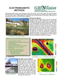
3 However, even a small site will often have widely varying soil resistivity from one spot to another. Using a four-point soil resistivity tester, many measurements must be made, and samples of the soil must be taken from several test locations and analyzed for both moisture and temperature. The actual measurement technique using the four-point tester is illustrated in Figure 1. Note that at least ten measurements are recommended to properly assess the site soil resistivity . Large areas require more measurements, but ten should be the minimum. Only soil to a depth of 10 feet (3 meters) needs to be tested in most situations.
4 In very unusual situations, more specifically in very dry areas or under extreme conditions, refer to the test meter instructions for the procedure required to assess resistivity as a function of depth. Table 1 lists some common soils and their resistivity . When the measurements are completed, the soil resistivity should be calculated, its temperature measured and the moisture content assessed. Moisture content is assessed by taking a representative soil sample at a depth of about 1 foot ( meter) and putting it in a plastic bag immediately. The weigh the sample, dry it out completely and weigh it again.
5 Express the difference as a percentage, with the result being the soil 's percent moisture by weight. TMLightning Eliminators & Consultants, Inc. - 2 - Designing for a Low Resistance Earth Interface -Rev. B-102407 Figure 1: soil resistivity Testing Using Four Point Method Figure 1 Notes 1. Distance between probes (A) should equal twenty times depth of probes (B). 2. soil resistivity in ohm-meters is equal to times the instrument reading when A equals 10 feet and B equals 6 inches. Table 1: soil Resistivities (approximate ohm-meters) soil Description Median Minimum Maximum Topsoil, loam 26 1 50 Inorganic clays of high plasticity 33 10 55 Fills ashes, cinders, brine wastes 38 6 70 Gravelly clays, sandy clays, silty clays, lean clays 43 25 60 Slates, shales 55 10 100 Silty or clayey fine sands with slight plasticity 55 30 80 Clayey sands, poorly graded sand-clay mixtures 125 50 200 Fine sandy or silty clays, lean clays 190 80 300 Decomposed gneisses 275 50 500 Silty sands, poorly graded sand-silt mixtures 300 100 500 Clayey gravel, poorly graded gravel, sand-clay mixture 300 200 400 Well graded gravel.
6 Gravel-sand mixtures 800 600 1,000 Granites, basalts, etc. 1,000 --- --- Sandstone 1,010 20 2,000 Poorly graded gravel, gravel-sand mixtures 1,750 1,000 2,500 Gravel, sand, stones, little clay or loam 2,585 590 4,580 Surface limestone 5,050 100 10,000 Table 1 Notes 1. Low- resistivity soils are highly influenced by the presence of moisture.
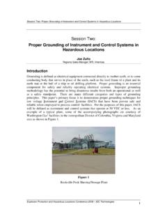
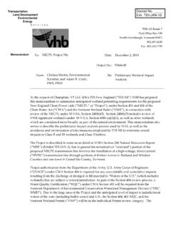
7 Lightning Eliminators & Consultants, Inc. - 3 - Designing for a Low Resistance Earth Interface -Rev. B-102407 2. Low- resistivity soils are more corrosive than high- resistivity soils. The percent of moisture and the temperature measurement should be compared with Figures 2 and 3, respectively, to determine the actual soil resistivity under optimum and worst-case conditions. This will permit a calculation of the range in grounding Resistance achievable in that soil with the final system design. The required design data has now been defined, and the design process can start from a solid foundation, , the required parameters.
8 The initial calculations should be based on the measured resistivity , and the final system design must take into account the extreme moisture and temperature variations. Variations of about 250 percent are normal for conventional systems. Figure 2: The Influence of Moisture Content Figure 3: The Influence of Temperature 200K160K120K80K40K04812162024 MOISTURE BY PERC EN TAG ERESISTIVITY, OHM- CMClayTopSo i lSandyLo a mLightning Eliminators & Consultants, Inc. - 4 - Designing for a Low Resistance Earth Interface -Rev. B-102407 Design Step 1: Calculating the Requirements with Conventional Ground Rods From the IEEE and other references, we know that the Resistance of any vertical grounding electrode R1 may be calculated from the following equations: English Units Metric Units (1) Where.
9 = soil resistivity in ohm-meters L = Electrode length in feet (English units) or in meters (metric units) d = Electrode diameter in inches (English units) or in meters (metric units) For example, if the soil resistivity averaged 100 ohm-meters, then the Resistance of one three quarter inch by 10 foot long electrode to true Earth would be found to be or ohms. Obviously, that is high and most likely not acceptable. The next step is to determine how many of these rods RN are required to achieve a given target Resistance goal. Design Step 2: Calculating the Required Number of Ground Rods Where: R1 = Resistance of one vertical ground rod (2) K = Combining factor ln (N) + N = Number of rods required (when they are properly deployed) Since making an electrical connection to Earth involves a connection between a conductor and a semiconductor, it is not point-to-point contact but conductor-to-area contact.
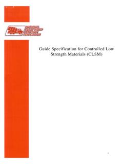
10 That is, making an electrical contact with Earth requires a significant volume of that Earth around the conductor to complete the connection. This can best be illustrated by considering the implications of the data presented by Figure 4, which illustrates the result of measuring the change in Resistance of equal segments of Earth along any radial from a driven rod. Notice that the change in measured Resistance decreases exponentially with distance from the rod, as illustrated by Figure 4. = NKRRN1= = Lightning Eliminators & Consultants, Inc. - 5 - Designing for a Low Resistance Earth Interface -Rev.