Transcription of DETAILED PROJECT REPORT FOR 50 KWp GRID CONNECTED …
1 DETAILED PROJECT REPORT FOR. 50 KWp GRID CONNECTED . Roof Top SOLAR PV POWER PLANT. Customer: M/s. SRM INSTITUTE OF SCIENCE AND TECHNOLOGY. Plant Location: KATTANKULATHUR. Page 1 of 45. INDEX. CHAPTER 1: GLOSSARY .. 3. CHAPTER 2: EXECUTIVE SUMMARY .. 7. CHAPTER 3: PROJECT 10. CHAPTER 4: 11. CHAPTER 5: LOCATION AND INFRASTRUCTURE 20. CHAPTER 6: IRRADIATION 21. CHAPTER 7: SELECTION OF PV 23. CHAPTER 8: POWER PLANT SCHEME .. 32. CHAPTER 9: POWER PLANT COMPONENT DESCRIPTION .. 36. CHAPTER 10: DESIGN OF THE POWER 41. CHAPTER 11: PROJECT IMPLEMENTATION AND SCHEDULE .. 42. CHAPTER 12: BILL OF MATERIAL .. 45. Annexure: I Single Line Drawing Annexure: II Site Photo Page 2 of 45. CHAPTER 1: GLOSSARY. Photovoltaic The physical effect of direct Conversion of light (sunlight) to electrical energy PV Cell The smallest photovoltaic (PV) element that generates electricity from light.
2 PV Module A collection of interconnected PV cells, encapsulated between protective materials such as glass and back sheet (Poly Vinyl Fluoride) or glass and glass, and mounted in an aluminum frame. This is a hermetically sealed unit. String Multiple PV modules CONNECTED in series electrically. Array Several strings of modules with the same orientation and tilt angle, located together. Inverter An electronic device that converts direct current electricity into alternating current electricity suitable for feeding directly to the electrical grid or to normal AC loads. Insolation It is a measure of solar radiation energy received on a given surface area in a given time. It is commonly expressed as average irradiance in watts per square meter (W/m ) or kilowatt-hours per square meter per day (kW h/(m day)) (or hours/day). Solar Irradiation The total electromagnetic radiation emitted by the Sun.
3 STC Standard Test Conditions - Incident Solar Irradiance of 1000. Watts/m2, at a spectral density of and cell temperature of 25 C. Mounting Structure Device used to hold modules in place, at desired angle & direction Page 3 of 45. Power Evacuation Power generated from Solar PV Power Plant is transmitted to a point (sub station) where it is distributed for consumer use. Sub-station The place where the generated power from solar is synchronized with utility grid and metered. Control Room A room housing control equipment. Cable A conductor with one or more strands bound together, used for transmitting electrical energy. Efficiency The ratio of the output to the input of any system. Junction boxes Inputs of several strings are CONNECTED to this box and taken as single output Current A flow of electricity through a conductor measured in Amps. Voltage The rate at which energy is drawn from a source that produces a flow of electricity in a circuit; expressed in volts It is the difference of electrical potential between two points of an electrical or electronic circuit, expressed in volts.
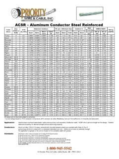
4 It is the measurement of the potential for an electric field to cause an electric current in an electrical conductor . Lightning Arrestor Device used to protect all the components from lightning strikes Earthing Described as a system of electrical connections to the general mass of earth Transformer An electrical device by which alternating current of one voltage is changed to another voltage Grid A system of high/low tension cables by which electrical power is distributed throughout a region Page 4 of 45. Abbreviations (Table 01). AB Air Breaker ACB Air Circuit Breaker AC Alternate current acsr aluminum Conductors steel reinforced BOS Balance of the System CDM Clean Development Mechanism CER Carbon Emission Reduction CO2 Carbon Dioxide CT Current Transformer DAS Data Acquisition System DC Direct Current DP Double Pole DPR DETAILED PROJECT REPORT HSEB Haryana State Electricity Board HT High Tension LT Low Tension LV Low Voltage MNRE Ministry of New and Renewable Energy kWh Kilo Watt Hour NO2 Nitrous Oxide MCB Main Combiner Box / Miniature Circuit Breaker MFM Multi Function Meters PLF Plant Load Factor PFC Power Finance Corporation PPA Power Purchase Agreement PV Photo Voltaic PT Power Transformer SEB State Electricity Board SO2 Sulphur Dioxide SP Single Pole UNFCCC United Nations Framework Convention on Climate Change VCB Vacuum Circuit Breaker XLPE Cross Linked Polyethylene
5 Page 5 of 45. Units (Table 02). % Percentage C Degree Celsius h Hour kV Kilo-Volt kW kilo Watt kWp kilo Watt Peak m meter m2 Square meter m3 Cubic meter mg milligram mm milli-meter MW Mega Watt MWp Mega Watt peak Page 6 of 45. CHAPTER 2: EXECUTIVE SUMMARY. 1. India is both densely populated and has high solar insolation, providing an ideal combination for Solar Power in India. Power is the lifeline of any development of the nation. At present the power requirement is being met by three main sources viz., Thermal, Hydel and Nuclear. While Hydel and Nuclear have their inherent limitations, Thermal Power is often confronted by the challenge associated with the availability of fuel. Currently Thermal Power stations which meet the major part of the power demand use coal as fuel. Conventional fuels such as oil, gas and coal cannot meet the increasing demand forever.
6 In addition to the requirement of huge funds, the implementation of more such projects using conventional means of power generation will also involve issues of growing environmental concern, with depletion of fossil fuels. 2. In order to bring down the dependence of finite fossil fuel for power generation, it is necessary to look into the viability of generating power locally using renewable energy sources. 3. Fortunately, India lies in sunny regions of the world. Most parts of India receive kWh of solar radiation per square meter per day with 300-325 sunny days in a year. India has abundant solar resources, as it receives about 3000 hours of sunshine every year, equivalent to over 5,000 trillion kWh. India can easily utilize the solar energy. Today The Government is encouraging generation of electricity from various renewable energy sources such as wind, solar, small hydro, biomass by giving various fiscal & financial incentives.
7 This apart, the state governments are procuring electricity from renewable energy projects at preferential tariff. So far 29,536 MW of renewable power capacity have been installed in the country, which includes 19,933 MW from wind, 2079. MW from solar, 3746 MW from small hydro and 3776 MW from bio energy. The Ministry of New and Renewable Energy is providing various renewable energy systems for decentralized generation of electricity. So far, 10,752 villages have been electrified using various renewable energy systems. About lakh solar street lights, lakh solar home lightening systems, lakh solar lanterns and 138 MW of decentralized solar power plants have been installed. 4. Government of India has separately set up a Ministry called MNRE - Ministry of New Renewable Energy for the promotion of Power Generation through Renewable Energy. The Ministry has been facilitating the implementation of broad spectrum program's including harnessing renewable power/ Energy( make use of one), renewable energy to rural areas for lighting, cooking and motive power, use of renewable energy in urban, industrial and commercial applications and development of alternate fuels and applications.
8 Page 7 of 45. 5. MNRE has announced a host of fiscal incentives such as concessional custom duties, exemption of excise duty and accelerated depreciation for Solar PV based Power Plants. At the State level, promotion of Solar Power generation is being encouraged by local policies that cover buy back, wheeling and banking of the generated electricity by State Electricity Boards, besides other incentives. 6. Considering the good potential of Solar Power and also the trust given by the Central & State Government in utilizing the abundant Solar Power in the State of Tamil Nadu for Power generation, M/s SRM INSTITUTE OF SCIENCE AND TECHNOLOGY is proposing to set up 50 KWp Roof Top Solar PV based Power Plant in Tamil Nadu state. 7. This Technical Proposal highlights the implementation of 50 KWp Solar PV based Power generation PROJECT at Tamil Nadu state under Independent Power Producer (IPP) mode.
9 8. The proposed Power Plant will have Solar PV modules, String Inverters as the major components & other accessories for the Power production. 9. All the necessary auxiliary facilities of the Power Plant like Plant Monitoring system, Safety equipments, Instrumentation, Control system etc., will be provided for the Power Plant. The water requirement for the module cleaning & for other requirements can be met from bore-wells at site. 10. The site selection for a Solar Power Plant is pre-dominantly determined by solar isolation availability & grid connectivity for exporting power. The proposed site where M/s SRM. INSTITUTE OF SCIENCE AND TECHNOLOGY Power Plant is to be located in Tamil Nadu is found favoring the above factors to a great extent. 11. The Plant and equipment facilities will be designed to comply with all applicable stipulations /. guidelines of statutory authorities such as State and Central Pollution Control Boards, Electrical Inspectorate, Inspector of Factories etc.
10 12. The net send out Power available from 50 KWp Power Plant is estimated to be 89 MWh per annum for crystalline modules. Page 8 of 45. 13. For the purpose of this REPORT , it is considered that the capital requirement of the PROJECT will be met by M/s SRM INSTITUTE OF SCIENCE AND TECHNOLOGY. 14. This REPORT highlights the details of the proposed Power generation scheme, site facilities, features of the main plant, electrical systems evacuation of generated power, environmental and safety aspects, distribution mechanism, Cost estimation, risk mitigation plan and PROJECT viability. It also highlights the complete schedule for the PROJECT implementation. Page 9 of 45. CHAPTER 3: PROJECT SUMMARY. SRM INSTITUTE OF SCIENCE AND. 1. Name of the Company TECHNOLOGY. 2. Proposed PROJECT Location KATTANKULATHUR. 3. District Name Kanchipuram 4. State Tamil Nadu 5.