Transcription of Determination of maximum span between pipe …
1 SHORT PAPER International Journal of Recent Trends in Engineering, Vol. 1, No. 6, May 2009 46 Determination of maximum span between pipe supports using maximum bending stress theory. Dr. Vakharia1, Mohd. Farooq A2 National Institute of Technology, Surat 395 007, Gujarat, India Email: National Institute of Technology, Surat 395 007, Gujarat, India Email: Abstract:- Straight cross-country pipelines are supported throughout the length of pipeline on different forms of supports at more or less regular spans. Maximizing the distance between supports will minimize the number of supports required, which in turn reduce the total cost of erecting these pipe supports. ASME has suggested the standards for support span , but the bending stress considered in its calculation is very low ( Mpa). There are other references also who have listed the maximum support span .
2 In this paper equations for calculating the maximum span using maximum bending stress are given. Safety of the design is checked using maximum deflection. A sample problem is considered for evaluation and the results thus obtained are compared with standards like ASME , U S Army Engineer s Manual and other references. The problem is also modeled in ANSYS and analyzed for deflection. A method of optimizing the distance between supports using ANSYS optimization technique is also discussed. Index Terms Introduction, Procedure for calculation of maximum span , Sample calculation & results, Comparative analysis, Computer analysis, Optimization, Conclusion. I. INTRODUCTION The cross-country pipelines are mainly supported on metal pipelines. The material is usually alloy metal, which is chosen based on the fluid to be transported. These pipelines are supported on different forms of supports viz, Metal in RCC supports, Metal frame supports, Small Trusses, etc.
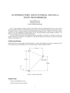
3 If the distance between the supports is maximized, the number of supports required throughout the length of pipeline will reduce. Thus, reducing the total cost of erection. Supports for piping must be spaced with respect to three considerations: [1]. a) Ability to place a support at some desired location. b) Keeping sag in the line within limits that will permit drainage. c) Avoiding excessive bending stresses from the uniform and concentrated loads between supports. This paper is based on determining the maximum distance between supports with respect to considerations (b) & (c). Fig. 1, shows the picture of a pipeline supported on two supports. A. Need Of Pipe Support The layout and design of piping and its supporting elements shall be directed toward preventing the following: (a) Piping stresses. (b) Leakage at joints. Figure 1.
4 Straight pipe resting on two supports (c) Excessive thrusts and moments on connected equipment (such as pumps and turbines). (d) Excessive stresses in the supporting (or restraining) elements. (e) Resonance with imposed or fluid-induced vibrations. (f) Excessive interference with thermal expansion and contraction in piping which is otherwise adequately flexible. (g) Unintentional disengagement of piping from its supports. (h) Excessive piping sag in piping requiring drainage slope; (i) Excessive distortion or sag of piping ( , thermoplastics) subject to creep under conditions of repeated thermal cycling. (j) Excessive heat flow, exposing supporting elements to temperature extremes outside their design limits. II. PROCEDURE FOR CALCULATION OF maximum span Design formulas for calculating bending stress and deflection between supports are derived from the usual beam formulas, which depend upon the method of support and the type of loading.
5 2009 ACADEMY PUBLISHERSHORT PAPER International Journal of Recent Trends in Engineering, Vol. 1, No. 6, May 2009 47 maximum Bending stress, S b = IDLwwLc) (2+ in N/m2 [1]. (1) maximum Deflection, y = EILwwLc3848534+ in meter [1]. (2) Where, w = uniformly distributed weight of pipeline in N/m w c = concentrated weight on pipeline in N L = span length in m D = Outside diameter of pipe in m d = Inside diameter of pipe in m E = Modulus of elasticity of pipe in N/m2 I = Moment of Inertia of pipe in m4 Note : maximum bending stress of the pipe can be taken as 30% of allowable stress. A. Calculation of total weight Total weight = weight of pipe (wp) + weight of fluid (wf) B. weight of pipe Thickness of pipe can be calculated as : t = )(2 PYESPxDa+ [4]. (3) Where, P = Pressure of the fluid in pipe in N/m2 S a = Allowable stress in pipe in N/m2 E = Quality Factor from ASME B Y = Coefficient of material from ASME B OR The thickness of the pipe can be directly accessed from [2].
6 Corrosion and other allowances are subtracted from this thickness. Now from this thickness, schedule of pipe can be decided which will give inner diameter of pipe. Annular cross-sectional area of pipe = 4 (D2 - d2) Hence weight of pipe can be calculated as, 4 (D2 - d2) x density of pipe material (4) OR The weight of Stainless Steel pipe can be directly calculated as , wp = (D-t)t [5] C. Calculation of weight of fluid Weight of fluid = 4 d2 x density of fluid in N/m (5) III. SAMPLE CALCULATION & RESULTS Let us calculate the maximum support span for transporting water through a seamless stainless steel pipe (ASTM A 312 TP 316 L) of 300 NPS through a distance of 15 km. Pressure in pipe is 20 bar at atmospheric temperature using the procedure described above. D = m [2] P = 20 bar S b = MPa (30% of S a = MPa) [4] Therefore, using equation (3), thickness of pipe comes out to be 6 mm.
7 Note : Schedule 20 is the nearest schedule for this thickness and according to thumb rule, the next schedule of pipe is finally selected, which is schedule 30. Schedule 30 gives a thickness of mm. [2]. Hence, d = m [2]. Weight of stainless steel pipe is calculated N/m [5]. Weight of water = N/m Total weight = N/m Moment of inertia = x 10-4 m 4 Modulus of Elasticity = 195122 MPa Substituting the above values in the maximum bending stress equation: (Since the pipe is not considered to carry flanges, it will not carry any concentrated load; hence 2nd element of equation is eliminated) maximum span between supports is calculated as meters, which is rounded back to meters. Hence number of supports required for 15 km pipeline is approx. 1364. With the above values, deflection comes out to be mm, which is less than 600L, Hence the calculated span is also safe in deflection. IV. COMPARATIVE ANALYSIS Table 1 shows a comparative analysis of the span shown in different tables marked in references.
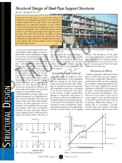
8 It can be seen that for the sample pipeline of 15 km length, the minimum number of supports required is calculated by the procedure described in the paper. 2009 ACADEMY PUBLISHERSHORT PAPER International Journal of Recent Trends in Engineering, Vol. 1, No. 6, May 2009 48 TABLE 1 COMPARATIVE VALUES OF span Sr. No. References Values of maximum span for SS pipe 300 NPS filled with water (meters) No. of supports required for a pipeline across 15 km 1 [Fig. 2] 2143 2 [6] 1622 3 [7] 1500 4 [8] 1500 5 Calculated 1364 Figure 2. Support span table from ASME B V. COMPUTER ANALYSIS The sample problem considered in the previous section is modeled in ANSYS.
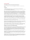
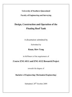
9 The calculated value of the span is used to model the problem and the deflection of the pipe is evaluated. The model is constrained at the end so that the end does not move under application of force. The total weight of the dead load plus weight of the working fluid is applied at the centre. Fig. 3 shows the model of the problem considered. Fig. 3. Model of the problem on ANSYS screen Fig. 4 shows the deflection of pipe under uniformly distributed loading on ANSYS screen. Figure 4. Deflected model of pipeline on ANSYS screen Fig. 5 shows the result from ANSYS analysis. It shows that a maximum deflection of mm takes place, which is a little higher than what was calculated ( , mm). But in any case the value of deflection remains less than 25 mm , Length of pipeline/600. Both analytical and computational results say that the results obtained in the previous section are safe.
10 2009 ACADEMY PUBLISHERSHORT PAPER International Journal of Recent Trends in Engineering, Vol. 1, No. 6, May 2009 49 Figure 5. Results obtained from ANSYS analysis VI. OPTIMIZATION Using the optimization technique of ANSYS version , distance between the supports can be optimized. First the pipeline with the calculated maximum span is modeled in the software and the analysis is done to find the stresses and deflection. The results of the analysis are stored and taken as reference for optimization. The design variables for optimization will be bending stress and deflection and the objective variable will be the span of supports. Limits for the design variables are defined and the objective variable will be given a value of highest order. The software using its first order method of optimization will try to achieve that maximum value while keeping the values of the design variables within the limits.