Transcription of DETERMINATION OF TRAJECTORY OF MATERIAL LEAVING …
1 Int. J. Mech. Eng. & Rob. Res. 2015 Faiz Abdulkadar Mulla, 2015. ISSN 2278 0149 Vol. 4, No. 1, January 2015. 2015 IJMERR. All Rights Reserved Research Paper DETERMINATION OF TRAJECTORY OF MATERIAL . LEAVING THE belt conveyor BY THE. MS-EXCEL PROGRAM AND TRANSPORTING. CORRESPONDING COORDINATES TO CADIAN/. AUTOCAD SOFTWARE WINDOW. Faiz Abdulkadar Mulla1*. *Corresponding Author: Faiz Abdulkadar Mulla, For design of discharge openings and receiving chutes, it is necessary to know the TRAJECTORY of MATERIAL LEAVING the head pulley in a conveyor system. TRAJECTORY of MATERIAL is fixed by the angle of separation of MATERIAL from the belt and the vertical ordinates from the tangent line drawn at the point of separation on head pulley. This program is for plotting the MATERIAL Discharge Trajectories for any belt - conveyor system viz.
2 , Horizontal/Incline/Decline belt Conveyors. This program has been developed on MS-Excel platform and its output is available for use in drafting software like CADIAN/AUTOCAD, etc. Keywords: belt conveyor , CADIAN/AUTOCAD, MS-EXCEL, Pulley, TRAJECTORY INTRODUCTION where The following procedure has been extensively V = belt Speed (m/s). in use for plotting of the MATERIAL discharge trajectories. rp = Radius of the pulley (m). DETERMINATION OF POINT DETERMINATION OF. OF SEPARATION ORDINATES. The angle of separation, that is, the angle from The length of vertical ordinates h1, h2, from vertical at which MATERIAL will leave the belt as point at equal intervals placed on tangent line it travels over discharge pulley is calculated drawn at the point of separation are calculated from the following formula: from the following formula: cos V2/( ).
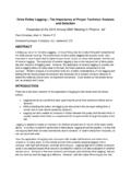
3 (1) h1 = gl12/(2V2), h2 = gl22/(2V2). 1. Assistant Professor, Walchand College of Engineering, Sangli, 32, Ashish, Near Kuber Vinayak Mandir, Ajinkya Colony, Powai Naka, Satara 415001. 336. Int. J. Mech. Eng. & Rob. Res. 2015 Faiz Abdulkadar Mulla, 2015. For guidance the value of ordinates h1, h2, GRAPHICAL. in metres with l = m per m/s of belt REPRESENTATION OF. speed are given below: TRAJECTORY OF MATERIAL . Table 1: xxxxxxxxxxxxxx The graphical representation of TRAJECTORY of h1 h2 h3 h4 h5 MATERIAL indicates the actual path which will be followed by the MATERIAL after it leaves the h6 h7 h8 h9 h10 discharge pulley. The TRAJECTORY of the MATERIAL depends upon the configuration of the belt h11 h12 h13 h14 h15 conveyor and is graphically represented in the manner laid down in A and B. Figure 1: Ordinates of the TRAJECTORY 337.
4 Int. J. Mech. Eng. & Rob. Res. 2015 Faiz Abdulkadar Mulla, 2015. For Ascending and Horizontal Belts With centre of pulley as the origin of the XY- If cos < 1 then the tangent line shall be drawn Coordinate system, forming algebraic at the point of separation (see Figure 1). If cos equations for each possible case of the = 1, the tangent line shall be drawn in the TRAJECTORY (Parabolic Path) and using MS- direction of belt travel (see Figure 1). Excel platform many coordinates representing the TRAJECTORY are derived. For Descending Belts If cos < 1 and angle of separation is more Transporting XY-Coordinates of than angle of inclination, , of the conveyor belt the TRAJECTORY to CADIAN/. AUTOCAD Software then the tangent line is drawn at the point of separation (see Figure 1). If cos 1 and is 1. XY-coordinates of the TRAJECTORY with centre less than or equal to angle of inclination, , of of pulley as O (0, 0) will be shown on the conveyor belt , the tangent line shall be drawn sheet named autocad.
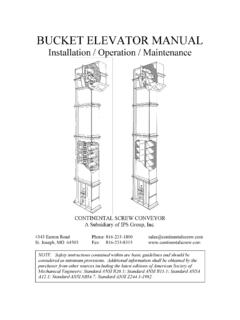
5 Save this as CSV. in the direction of belt travel (see Figure 1). (Comma delimited) file. Open this. CSV file with notepad and write in the first line PLINE. For drawing the TRAJECTORY of top of the and then press enter once. Then save this stream of MATERIAL of height H1, the radius rp in notepad file as SCRIPT FILE (SCR). Just formula (1) is replaced by (rp + H1) and velocity drag this SCRIPT file over the window of V by: the DRAFTING SOFTWARE and will get the V . (rp + H1)/rp plot of a TRAJECTORY required. Figure 2: TRAJECTORY of the MATERIAL (in CADIAN/AUTOCAD). 338. Int. J. Mech. Eng. & Rob. Res. 2015 Faiz Abdulkadar Mulla, 2015. 2. Explode this transported figure and delete CONCLUSION. two straight lines. Then draw circle with The Coordinates as Obtained from the program centre O (0, 0, 0) representing the pulley of and calculated manually are in close the specified radius and making block of agreements.
6 Using this program, industry can the same entire figure could be shifted to save many man hours with increased accuracy of the plot and thereby have huge cost reduction any place in the window of the drafting in the design process of conveyor system. software. 3. Finally the plot of the TRAJECTORY would be as REFERENCES. shown in the Figure 2. 1. conveyor Equipment Manufacturers Association (1997), 5th Edition, CEMA. 4. If discharge pulley is on the left hand side of Book. the conveyor system, then the mirror image 2. MATERIAL Handling Engineers Association, of the above plot can be utilized. 1986. 339.