Transcription of Determining Energy Requirements - Air & Gas Heating
1 Chromalox Technical Documents Technical Technical Information Determining Energy Requirements - Air & Gas Heating Air & Gas Heating Graph G-176S Air Heating Low Temperature Heater Selection A. 170. 0 F se ypical heater selection for the previous 550 ise Based on Air Density of e Air and gas Heating applications can be divided se Ris 50 F Ri Lbs/Ft3 and a Specific R. Ri into two conditions, air or gas at normal example might be a type CAB heater with F. Heat of Btu/Lb/ F. F. 600. finstrip elements. Available 15 kW stock 0. atmospheric pressure and air or gas under low 150. 45. ise to high pressure. Applications at atmospheric heaters include a CAB-1511 with chrome FR. 0 . pressure include process air, re-circulation and steel elements or a CAB-152 with iron sheath 40. 130. elements, both rated at 26 W/in2. From the ise oven Heating using duct or high temperature FR. insert air heaters. Pressurized applications product page, the face area of a 15 kW CAB. 0.
2 35. include pressurized duct Heating and other 110 se heater is ft2: processes using high pressures and circula- Ri F. tion heaters. Procedures for Determining heat 0 Velocity (fps) = 450 ACFM = fps 30. Energy Requirements for either condition are 90 ft2 x 60 sec. ise Kilowatts similar except the density of the compressed FR. 0 Estimating Sheath Operating Temperature gas and the mass velocity of the flow must be 25. 70. e The maximum operating sheath tempera- considered in pressurized applications. Selec- Ris tion of equipment in both conditions is critical 0 F tures for finstrips are 750 F for iron and 950 F. 20. due to potentially high sheath temperatures 50 e for chrome steel. Using graph G-107S for iron Ris sheath finstrips, a 150 F outlet temperature that may occur. F. 150 and a watt density of 26 W/in2 requires a 30 se velocity in excess of 9 ft/sec to keep sheath Determining Heat Requirements for F Ri 100 temperatures below maximum permissible Atmospheric Pressure Gas Heating Rise 75 F levels.
3 With only fps in the application, a 10 ise 50 F R CAB-152 heater with iron sheath elements is The following formulas can be used to deter- 10 not suitable. Using graph G-108S for chrome mine kW required to heat air or gas: sheath finstrips, approximately 3 ft/sec. air 0. Equation A 100 300 500 700 900 1100 velocity results in a maximum of 900 F sheath Air Volume (Cubic Feet Per Minute) temperature. Since this is lower than the kW = CFM x lbs/ft3 x 60 min x Cp x T x SF actual velocity of fps, a CAB-1511 with 3412 Btu/kW chrome steel finstrips is an acceptable heater Process Air Heating Calculation Example selection. (Use graphs G-100S, G-105S,G- Where: A drying process requires Heating 450 106S and G-132S for air Heating with regular CFM = Volume in cubic feet per minute ACFM of air1 from 70 F to 150 F. The existing strip and finstrip heaters.). Lbs/ft3 = Density of air or gas at initial duct- work measures 2 ft wide by 1 ft high and temperature is insulated (negligible losses).
4 To find Heating High Temperature Heater Selection Type Cp = Specific heat of air or gas at initial capacity required, use Equation A: TDH and ADHT heaters with tubular elements temperature are recommended for high temperature ap- T = Temperature rise in F kW = 450 ACFM x x 60 x x 80 x SF plications. Steel sheath tubulars may be used SF = Suggested Safety Factor 3412 Btu/kW where the sheath temperature will not exceed 750 F. Finned tubulars can be used in applica- For quick estimates of air Heating require- kW = tions up to a maximum sheath temperature of ments for inlet temperatures up to 120 F, the 1050 F. INCOLOY sheath tubulars may be following formula can be used. Heater Selection used for applications with sheath temperatures up to 1600 F. Allowable watt densities for tu- kW = SCFM x T x SF Finstrip (CAB heaters), Fintube (DH heaters). or tubular elements (TDH, ADH and ADHT bulars and finned tubulars can be determined 3,000 by reference to graphs G-136S and G-151-1.)
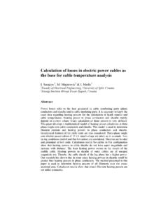
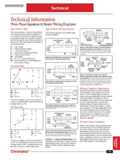
5 Heaters) will all work satisfactorily in low Where: temperature applications. Finstrips or finned through G-156-1. SCFM = Volume of air in cubic feet per minute tubular elements are usually the most cost at standard conditions1 (70 F at Estimating Sheath Operating Temperature effective. Tubular elements are recommended Select a heater for a high temperature standard atmospheric pressure) for high temperatures. Once the desired type 3,000 = Conversion factor for units, time and application with an inlet air temperature of of Heating element is selected, the next step 975 F and a velocity of 4 ft/sec. Since the Btu/lb/ F is to calculate the air velocity and estimate temperature is above 750 F, an INCOLOY . SF = Suggested safety factor of 20% sheath temperatures to verify that maximum sheath must be used. Using graph G-152-1. Graph G-176S When airflow (ft3/min) and operating temperatures are not exceeded. the allowable watt density is 11 W/in2 for temperature rise are known, kW Requirements Calculate the air velocity over the elements sheath temperatures of 1200 F or 22 W/in2 for can be read directly from graph G-176S.
6 And refer to allowable watt density graphs for temperatures of 1400 F. In this application, Note Safety factors are not included. estimated operating temperature. a stock ADHT heater2 with a standard watt density of 20 W/in2 can be used. Calculating Air Velocity Air velocity can be Note 1 Based on an average density of calculated from the following formula: Note 2 Special ADHT duct heaters, derated lbs/ft3 and a specific heat of Btu/lb/ F. For greater accuracy, use Equation A and values to the required watt density, can be supplied Velocity (fps) = Flow (ACFM). from the Properties of Air Chart in this section. when element ratings less than the standard Area of Heater (ft2) x 60 sec. 20 W/in2 are needed. I-16. Technical Technical Information Allowable Watt Density & Heater Selection - Air Heating Air & Gas Heating with Strip and Finstrip Heaters Custom Designs Strip and finstrip heaters Graph G-105S Strip Heater Air Heating -Selection of Watt Density are frequently mounted in banks by the end 20.
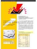
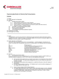
7 User. Graphs G-105S and G-106S on this page 700. can be used in conjunction with other graphs to determine maximum watt density for virtually any custom design low temperature Ai Heating application. rV 9. 600 15. elo 16. Chrome Steel Sheath cit Outlet Air Temperature ( F). Graph G-105S Strip Heaters y(. 4. To use this graph: .S..). 1. 500. 1. Select maximum desired outlet air W/In2. 10. temperature on line A. Air Ve 400 16 lo cit y(. 2. Choose either chrome steel sheath or rust Iron Sheath 9 . 4 S.). resisting iron sheath (points B) on the 300 1. basis of operating conditions. 5. 200. 3. Select minimum anticipated air velocity on B. Note natural circulation is equal 100. to approximately one foot per second. 0 0. 4. Draw a straight line through points A and A B C. B to a reading on C. Read maximum allowable watts per square inch from line C. 5. Select desired length heater with an equivalent watt density or less from the Graph G-106S Finstrip Heater Air Heating -Selection of Watt Density product page in this catalog.
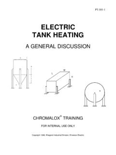
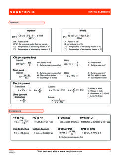
8 700.. Graph G-106S Finstrip Heaters To use this graph: 1. Select maximum desired outlet air 600. temperature on line D. 2. Choose either chrome steel sheath or rust resisting iron sheath (points E) on the basis of operating conditions. 30. 500. Outlet Air Temperature ( F). 3. Select minimum anticipated air velocity on B. Note natural circulation is equal Air 16. Ve to approximately one foot per second. 25. loc Chrome Steel Sheath 9. ity 4. Draw a straight line through points D and (F. 400. 4. E to a reading on F. Read maximum Ai rV..). 20. elo allowable watts per square inch from 16. 1. cit line F. W/In2. 9. y(. 300 Iron Sheath . 4. S. 5. Select desired length heater with an ). 15. equivalent watt density or less from the 1. product page in this catalog. 200. Recommendations for Custom Installations 10. Strip heaters should always be mounted INFORMATION. 100. sideways in the ductwork with the narrow TECHNICAL. edges facing the air stream. The total number of elements installed should be divisible by 3 0 5.
9 D E F. so that the heater load will be balanced on a three phase circuit. I-17. Technical Technical Information Allowable Watt Density & Heater Selection - Air Heating Graph G-132S Strip Heater (Iron) Air Heating Graph G-100S Strip Heater (Chrome) Air Heating Allowable Watt Densities for 700 F Sheath Temp. Allowable 26 Watt Densities for 1000 F Sheath Temp. Wattage Rating of Strip Heater = W/In2 x Heated Area Strip Heaters < 30-1/2", Heated Length = Overall Length - 4". Strip Heaters 30-1/2", Heated Length = Overall Length - 5" 24. 16. 15 1-1/2" Wide Strip Heater = in2/in. 14 .S. 16 F. 1" Wide Strip Heater = in2/in. 22 Di 13 str Watts Per Square Inch (W/In2). Dist ibu 12 ribu 9 F. te 9 ted d 11 S. Air Ai Vel 20 . r oci 10 4 ty Ve 9 S. lo ci t 8 1 18 4 F. or Free y 7 Air . Watts Per Square Inch (W/In2). 6. 5 16. 4 1 .S. o 3 When Calculating Heater Capacity, Use the r Free Maximum Outlet Temperature and the 14 Air 2. 1 Lowest Air Velocity. For Close Grouping of Heaters, Use 80% of the Calculated Value.
10 0 12. 0 100 200 300 400 500 600 700. Outlet Air Temperature ( F). 10.. Graph G-107S Finstrip (Iron Sheath) Air Heating 8. Allowable Watt Densities for 700 F Sheath Temp. 32 Wattage Rating of Finstrip = 6. 16 W/In2 x x Heated Length 28 9 .S..S. Dis 4. trib ute Watts Per Square Inch (W/In2). 24 4 dA.. ir V. elo 2 When Calculating Heater Capacity, Use the 20 cit 1 y Maximum Outlet Temperature and the Lowest or Free Air Velocity. For Close Grouping of Heaters, 16 Air 0 Use 80% of the Calculated Value. 12 0 100 200 300 400 500 600 700 800 900 1000. Outlet Air Temperature ( F). 8. When Calculating Heater Capacity, Use the Notes . 4 Maximum Outlet Temperature and the Lowest Strip Heaters < 30-1/2", Heated Length = Overall Length - 4". Air Velocity. For Close Grouping of Heaters, 0. Use only 80% of the Calculated Value Strip Heaters 30-1/2", Heated Length = Overall Length - 5". 0 100 200 300 400 500 600 1-1/2" Wide Strip Heater = Outlet Air Temperature ( F) 1" Wide Strip Heater = Graph G-108S Finstrip (Chrome Steel) Air Heating Graph G-136S Tubular Heater Air Heating Allowable Watt Densities for 900 F Sheath Temp.


![t } } o h o u Z ] o o ^ } o µ } v ^ ] u µ o v } µ , v P v ...](/cache/preview/d/5/8/c/b/5/3/4/thumb-d58cb53409acc8a3dc323250eb01b665.jpg)