Transcription of Development of 22-kV Distribution Systems and …
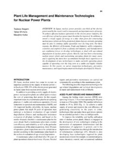
1 Development of 22 kV Distribution Systems and switchgear 158 Development of 22-kV Distribution Systems andSwitchgearOVERVIEW: As the demand for power has continued to grow in cities andother areas of concentrated power consumption, costs are rising due to thelack of sites to locate 6-kV Distribution substations and increasinglycongested Distribution conduits. This has led to a demand for power supplysystems and equipment that can boost Distribution per line capacity from 6kV to 22 kV, that can deliver loads close to where the power is consumed,and minimize power losses in Distribution which reduces CO2 emissionsand thus helps mitigate global warming. Standing in the way of greaterdeployment of 22-kV switchgear is that the equipment is larger and morecostly than prevailing 6-kV equipment. To address this situation, Hitachi,Ltd. joined forces with The Tokyo Electric Power Co., Inc. to develop morecompact and less expensive 22-kV Distribution KikukawaKenji TsuchiyaSatoru KajiwaraAkira TakahamaINTRODUCTIONALTHOUGH the availability of 6-kV Distribution inurban centers and other areas of concentrated demandfor power is quite high, the prospect of boosting 6-kVsupply further is fraught with difficulties: it has becomeextremely difficult to acquire sites for locating newpower Distribution substation due to rising land pricesand it has become harder to secure Distribution routesbecause power Distribution conduits are alreadycongested.
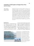
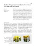
2 On the other hand, most of Japan s powerdistribution infrastructure in urban areas isunderground, so if excavation work is done to lay newFig. 1 Overview of 22-kV Distribution , which is inversely proportional to voltage, is substantially lower for 22-kV Distribution than forconventional 6-kV Distribution when the amount of power used is the same. In addition, 22-kV Systems give offless CO2 emissions since energy losses during Distribution are proportional to current squared, so 22-kVdistribution also helps reduce global line400 V/100 200 V transformerPMT: pad-mounted transformer. Often installed on the sidewalk. RNW: regular network. By interconnecting several RNWs on the low-voltage side, load can continue to be supplied from another system in the event one system fails. SNW: spot network. A spot network consists of the secondaries of three transformers connected together to maintain a constant source of supply even if one transformer fails.
3 22 kV/400 Vtransformer22 kV/6 kV transformer100 V/200 V230 V/400 V400 V22 kV22 kV6 kV400 V400 VLess than 50 kW(residence)50 500 kW(small building)500 2,000 kW(medium building)2,000 10,000 kW(large building)6-kVdistribution lineMini substationBranchcabinetPMTB ranchcabinetRNW Transformercabinet22-kVdistribution lineSNW Substation66 kV/22 kVHitachi Review Vol. 53 (2004), No. 3 159secondaries of two or more transformers and thereforecontinue to supply power even when one line is downfor inspection, and have a high degree of maintainabilityand are generally deployed as low-voltageSNWs in which transformer secondaries supply low-voltage power or as high-voltage SNWs in whichtransformer secondaries supply 6 kV to supportefficient Distribution within a single building (see ).(3) RNW*2 systemsRNW Systems maintain a constant source of supplyand are generally applied in bustling shopping areassuch as Ginza and Shinjuku in Tokyo.
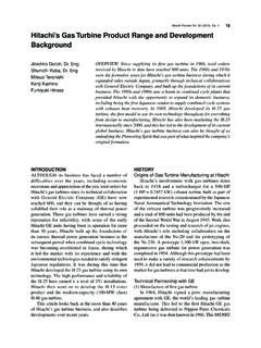
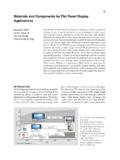
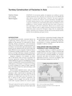
4 However, thissystem is not being expanded because of the numerousrequests from customers for 6-kV power and becausethe system is insufficient in maintainability, operability,Fig. 2 Schematic Single-line Connection for for main and backup line system (a) and SNWsystem (b).: Switch: Transformer: Circuit breaker22-kV Distribution line(a)(b) 22-kV Distribution linesMain lineBackup linedistribution feeders, it makes much more economicsense to deploy 22-kV Distribution lines that have aboutthree times the capacity of 6-kV lines. At the sametime we must keep in mind the need for existingsubstations to make effective use of 22-kV equipmentand the need to maintain efficient supply throughcentralized control of 6-kV Distribution Systems andpower primary obstacles standing in the way of furtherdeployment of 22-kV Distribution is that thisequipment is larger and more costly than comparable6-kV Systems .
5 Challenged to address this situation,Hitachi, Ltd. entered into an alliance with The TokyoElectric Power Co., Inc. to develop and deploy morecompact and less costly 22-kV Distribution this paper we highlight the main features andapplications of the Systems that emerged from this jointresearch initiative; specifically, a 22-kV distributionsystem, hybrid switchgear , 22-kV /6-kV large-capacitymini substations, 3 N connection transformer (three-phase three-wire single-phase division connection),and 22-kV PMT (pad-mounted transformer) (see ). 22-kV Distribution SYSTEMThe 22-kV Distribution is primarily directed aturban and other densely populated areas, and ourefforts are focused on reducing overall costs (bymaking the equipment more compact and reducingequipment costs), by enhancing the Distribution systemto ensure improved reliability and better optimize the Distribution efficiency fromsubstations, 22-kV power may be distributed to thepoint of demand where it is stepped down to 6 kV, orin other cases such as industrial zones and sparselypopulated regions, power may be supplied by 6-kVdistribution Systems .
6 Let us first consider the 22-kVsupply side equipment that is currently available1). 22-kV /Low Voltage Direct Supply(1) Main and backup line system and loop systemsThis is the most common system for receiving 22-kV power. Since it has somewhat smaller transformercapacity than SNWs (spot networks)*1, it is moreeconomical both in terms of space and cost, and istherefore extensively deployed (see Fig. 2).(2) SNW systemsSNWs are most commonly found in cities and otherareas of high demand, and are seeing increasingdeployment to exploit their advantages: SNWsmaintain a constant sources of supply, consist of*1 SNW: spot network. A spot network consists of the secondaries ofthree transformers connected together to maintain a constant source ofsupply even if one transformer fails.*2 RNW: regular network. By interconnecting several RNWs on the low-voltage side, load can continue to be supplied from another system in theevent one system of 22 kV Distribution Systems and switchgear 160conductor for connecting to the cable head at thebottom of the molded case, a current transformer formetering that is built into the epoxy molded insulatedhousing, a condenser for voltage detection, and three(for three phases) four-position vacuum switchesenclosed in a molded case (see Fig.
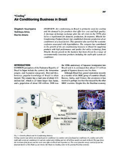
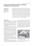
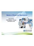
7 5).Insulation between the vacuum switches isaccomplished by a small amount of SF6 gas in theand SupplyA Distribution system has been supplied in which22 kV is distributed fairly close to customers, thenstepped down to 6 kV using a local mini we will describe the main/backup line system (mini substation).While this system has been applied to industrialzones and sparsely populated areas, it would also beeffective in densely-populated residential the environment where this system mightpotentially be deployed, we have focused on increasingthe capacity of the system while also making it system is useful not only for supplying 22-kV customers but also for supplying existing 6-kVcustomers. This not only serves as a transitional systempromoting the spread of 22-kV supply, it will alsopromote increasing application of mini substations (seeFig. 3).HYBRID switchgear 2)Hybrid switchgear SpecificationsThe main specifications of the hybrid switchgearare listed in Table switchgear ConfigurationThe hybrid switchgear consists of the (1) the main circuit section enclosing three three-phasefour-position vacuum valves, (2) an operation unit that operates vacuum switches, (3) and a control section featuring digital protection/metering equipment for protecting main circuits andmonitoring current and voltage (see Fig.
8 4).The main-circuit section consists of a cable-sideFig. 3 Schematic Single-line Connection for Mini transformer can handle a maximum capacity up to 10 1. Main Specifications of Hybrid SwitchgearNotable features include integration of switches and 4 External View of Hybrid unit measures 1,100 mm W 450 mm D 1,450 mm H(1,500-mm high including the base).Type of switchInsulation systemRated voltageRated currentRated frequency/phaseRated interrupting currentRated short time withstand currentWithstand voltage PowerfrequencyLightning impulse*1 In some case where less rigorous insulation requirements are called for, the SF6 gas may be replaced by CO2 gas, N2 gas, or dry air. *2 Figures in parenthesis show performance between circuit breaker,disconnect switch, and earth switchComposite insulation: vacuum,SF6 gas*1, and epoxy mold24 kV200 A, 400 A, 600 A50/60 Hz, three-phase25 kA25 kA 1s(main circuit, earthing circuit)50 kV (60 kV)*2125 kV (145 kV)*2 Main lineBackup lineTransformer 22 kV/6 kV 24-kV circuit circuit breakerOperation unitDigital protection/metering equipment Main-circuit section (enclosing vacuum valves)Hitachi Review Vol.
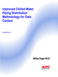
9 53 (2004), No. 3 161 Fig. 5 Internal Structure of Hybrid switchgear of four-position vacuum valve (a), and cut-away epoxy resin module showing circuitry (b).TABLE 2. Comparison of 22-kV /6-kV Mini SubstationSpecificationsThe new mini substations provide greater capacity, enhancedcapabilities (including built-in remote monitoring anddistribution line coupling capabilities), and are smaller thanprevious 6 External View of the 22-kV /6-kV Large-capacity new mini substation is already being delivered to The TokyoElectric Power Co., case and molded insulation plates between thevacuum switches. This composite insulation systemprovides enhanced its potential adverse effect on globalwarming, the amount of SF6 gas has been cut to severaltenths the level used in earlier versions of our gas-insulated LARGE-CAPACITY MINISUBSTATION 3)New construction of substations has fallen in thesluggish economy even as the demand for energy inurban areas has continued to grow.
10 To cope with thesecircumstances, we have seen an increasing number ofsmaller substations and deployment of large-capacitymini Mini Substation SpecificationsTable 2 shows the main parameters of the new minisubstations that we recently developed in comparisonwith the older Mini Substation: Key DevelopmentConsiderations(1) Smaller floor spaceIn order to reduce the floor space of the minisubstation, hybrid switchgear was used for the 22-kVincoming section, the transformer heat dissipater wasimplemented more compactly, and regular vacuumcircuit breakers were used for the 6 kV distributionsection. Even while adding remote monitoringequipment and remote control equipment, wesucceeded in reducing the floor space of the new miniBusFixed electrodeRotating electrodeMain axisMolded busbarSF6 gasFour-position vacuum switchEarthterminalCable connectionLoadBellowsGround conductor(b)(a)GroundDisconnectOffOnMold ed case(epoxy resin)Operating rodCTVDCT: current transformerVD: voltage detectionReceiving voltageDistribution voltageTransformer capacityLoad tap changerOperation room22 kV6 kV6 MVANoNoSameSame10 MVAYesYesRemote monitoring equipmentLocated separatelyBuilt-inRemote control equipmentLocated separatelyBuilt-in Floor m2* Already deliveredItemOld type*New typeDevelopment of 22 kV Distribution Systems and switchgear 162substations from m3 to m3 (see Table 2 andFig.)