Transcription of Development of Multilayer Flex Substrate with …
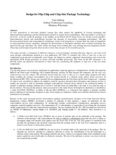
1 Development OF Multilayer flex Substrate with liquid crystal polymer FILM Hiroyuki Okabe, Nagayoshi Matsuo, and Kenji Saito Hitachi Cable, Ltd. Hitachi-shi, Ibaraki, Japan Kazunori Ueda Nippon Steel Chemical Co., Ltd. ABSTRACTIn accordance with prevalence of wireless Local Area Network (LAN) and electrical mobile devices such as cellular phones, Personal Digital Assistants (PDA) and notebook personal computers, massive and fast data transmission for handling sound and pictures is being required in small body size of a semiconductor package. In the evolution, substrates for packages also become smaller and thinner, accommodating more I/O terminals with appropriate electrical properties.[1] In this paper, the possibility of highly dense, reliable Substrate with liquid crystal polymer (LCP) material is discussed.
2 And electrical properties in high frequency are compared with conventional Substrate . Key words: LCP, BGA, Substrate , CSP BACKGROUND Chip Scale Package (CSP) is very popular to make mobile devices smaller and lighter, and glass epoxy material such as FR-4, or Bismaleimide-Triazine (BT) resin material, are widely used for substrates of CSPs. The core thickness keeps decreasing down to 60 m in production, but on the other hand, yield loss in manufacturing process as well as package assembly process becomes more serious than ever. For the further reduction of Substrate thickness, coreless film material like polyimide began to be used for CSPs. [2] Polyimide is chemically stable, and in addition, it has good thermal resistance and electrical properties. However, its rather high moisture absorption sometimes causes popcorn phenomenon in packages.
3 Recently liquid crystal polymer is highlighted as coreless material to cover such disadvantage of polyimide. Hereinafter, various performance of Substrate which is made of LCP film is clarified. BASIC PROPERTIES OF LCP LCP material is also chemically and thermally stable with good electrical properties. The most difference from polyimide is that LCP is thermoplastic material while polyimide is non thermoplastic. Using this feature, Multilayer Substrate can be formed with LCP film. Basic properties of LCP are shown in Table 1. Table 1 Properties of LCP All the data above were provided by Nippon Steel Chemical except (*) and (**). (*) : Measured by Hitachi Cable, Ltd. (**): Provided by Kuraray Co., Ltd. As is recognized in the table, moisture absorption of LCP is much lower than polyimide s.
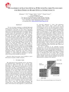
4 Fig. 1 is the data of moisture absorption / desorption in the comparison between LCP and polyimide. The rate of moisture absorption of LCP was approximate while that of polyimide s was Its desorption speed was very high. That means it is easy to get rid of water from Substrate by heating for short time, to reduce risks of moisture-related issues such as popcorn phenomena in packages. 625 Compared with polyimide, coefficient of humidity expansion of LCP is also very low. This helps position control in Substrate / assembly process. Tg of LCP is 275 C and is enough high comparing to temperature of soldering process. Its Coefficient of Thermal Expansion (CTE) is as low as 17ppm/ C, matched with the one of Copper (17ppm/ C).
5 Other advantages of LCP are low k properties especially in higher frequency than 1 GHz. This means that the possibility of the material is for RF modules, high speed devices and so on. MANUFACTURABILITY Using LCP and polyimide, 2 metal layer Substrate was made for comparison of properties. Design values of test samples are described in Table 2. The sample pattern was formed with subtractive method (etching method), and via holes were drilled by laser. Photo sensitive type of solder mask resin was applied over the circuit with openings for bonding pads, solder ball pads and other required features. Fig. 2 shows the appearance of the test sample with LCP Film. The difference of base film from polyimide did not bring significant issues in the process of Substrate manufacturing.
6 The cross section of minimum pitch circuit is shown in Test Sample Appearance (LCP) The leads were formed with high etching factor of about even in the fine pitch circuit of 60 m pitch, as it was got from polyimide base material. Photo solder mask on LCP was exposed and developed differently from on polyimide film as shown in Fig. 4. In the case of on LCP base film, the edge of photo solder mask became sloped while that on polyimide base film was almost vertical. Photo solder mask of negative type used in this evaluation is cured with Ultra Violet (UV) light in exposure process, and area exposed by UV light is cross-linked. The color of LCP is white and not Table 2 Design of Test Sample ItemLCPP olyimideSolder Mask2020 Gold Mask2020 PatternMin Line / Space25/3525/35 Via StructureBlind Via Blind ViaVia Diameter6060 Capture PadDiameter160160 SpecViaThickness( m)Ball SideChip Sidea.
7 Chip Side b. Ball Side Cross Section of 60 m Pitch (Hrs)Moisture Absorption (%)LCPP olyimidea. Moisture Absorption Rate (85 C 85%RH) (Hrs)Moisture Absorption (%)LCPP olyimideb. Moisture Desorption Rate (125 C) Fig. 1 Moisture Absorption 626transparent. It is thought that the reflection rate of the UV light at the interface between solder mask and LCP base film is much higher than that of polyimide. Because of the random reflection, the edge of photo solder mask on LCP base film is supposed to be exposed and sloped. This phenomenon is unique for on base film, and the edge of photo solder mask on copper pattern of LCP sample was as sharp and vertical as that of polyimide. Then it is thought that this sloped solder mask edge should not affect reliability such as ball joint on solder mask defined ball pad. Concerning via hole drilling, LCP film showed same level of manufacturability as polyimide film.
8 Fig. 5 is cross section of a via hole in LCP film and polyimide film. By the same conditions of laser drilling, diameter of via holes in LCP was rather larger than that in polyimide, but it is adjustable by change of laser conditions. Fig. 5 Via hole Cross Section RELIABILITIES Using same design test sample both with LCP base film and polyimide base film, reliabilities were evaluated. Prior to all the tests except solder float test, preconditioning of JEDEC Level 2 with reflow at 260 C was treated. For solder float test, only moisturizing with 85 C, and 60%RH for 168 hours was done before floating. Results of reliability tests are shown in the Table 3. It was found from the results that reliabilities with LCP were almost equivalent to polyimide s. LCP especially showed more stability in moisture test.
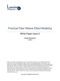
9 Fig. 6 is comparison of Thermal Humidity Biased (THB) test in 60 m pitch circuit between LCP and polyimide. According to the graphs, LCP showed equivalent moisture reliability to polyimide up to 1000hours, and the variation of resistance of LCP was smaller than that of polyimide. LCP has very low moisture transmission coefficient, and according to the data in the Table 1, the coefficient of LCP is approximate 1/800 of polyimide s. In the case of LCP, the film might become a barrier to moisture from the other side of circuit, which contributes to copper migration during THB test. CTE in z-direction of LCP is higher than that of polyimide. CTE mis-match to copper in z-direction sometimes causes via hole cracks in temperature cycle. Using via hole chain LCPP olyimideTopViewCrossSectionFig. 4 Cross Section of Photo Solder Mask a.
10 LCP b. Polyimide Table 3 Results of Reliability Tests + + + + + + +120100200300400500600700800900 1000 Duration (hrs)Electric Resistance ( )b. Polyimide Fig. 6 THB Test Results + + + + + + +120100200 300400500600700800900 1000 Duration (hrs)Electric Resistance ( a. LCP 627structure, the impact of CTE mis-match during temperature cycle was evaluated. Fig. 7 shows resistance change of via hole chain structures. By the results of the temperature cycle test, it was confirmed that in spite of higher CTE in z-direction, the resistance change of via hole chain was smaller than 5% and almost equivalent to the level of polyimide. In this case, the base film is very thin (25 m in thickness), and the impact of CTE mis-match to copper was not so big to cause via hole cracks. When the use of LCP in larger thickness, the CTE mis-match to copper should be revisited.)