Transcription of Development of Super Waste-Heat Recovery …
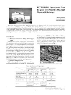
1 Mitsubishi Heavy Industries Technical Review Vol. 48 No. 1 (March 2011) 17 *1 Engineering Manager, Marine Machinery Design Department, Nagasaki Shipyard & Machinery Works *2 Manager, Marine Machinery Design Department, Nagasaki Shipyard & Machinery Works *3 Marine Machinery Design Department, Nagasaki Shipyard & Machinery Works *4 Research Manager, Nagasaki Research & Development Center, Technical Headquarters Development of Super Waste-Heat Recovery system for Marine Diesel Engines YOSHIHIRO ICHIKI*1 KEIICHI SHIRAISHI*2 TAKAYUKI KANABOSHI*3 YOSHIHISA ONO*3 YUJI OHTA*4 Mitsubishi Heavy Industries, Ltd. (MHI) has developed a Super Waste-Heat Recovery system for a main marine propulsion engine as a solution for strengthened environmental restrictions and increasing demand for improved fuel oil consumption.
2 In a conventional combined system , in which the exhaust gas from a main diesel propulsion engine is utilized in an exhaust gas economizer and a steam turbine generation system , all of the exhaust gas from the diesel engine passes through a turbocharger. The newly developed Super Waste-Heat Recovery system consists of a conventional combined system and a power turbine (gas turbine) that utilizes a portion of the exhaust gas with an automatic overrunning clutch between the power turbine and the steam turbine. In this system , the turbines are used to drive a generator. This is the first compound energy Recovery system for marine use in Japan. The steam and the power turbines have control systems to share the load according to the electricity requirements of the ship.
3 This system increases the electric generation capability by two or three times compared to a conventional waste heat - Recovery system and significantly increases the marine engine plant efficiency (relative value of 8% 10%) while reducing carbon dioxide emissions. MHI has an order to build 38 container ships using this system . These will be built by a Korean shipbuilder and delivered to a European owner. The first system was installed in a ship in November 2010 and subjected to sea trials, and is scheduled to be delivered to the owner in March 2011. |1. Introduction Conventional Waste-Heat Recovery systems for a main diesel marine propulsion engine supplies electricity to a ship using an exhaust gas economizer and a steam turbine. MHI has developed a Super Waste-Heat Recovery system consisting of a conventional combined system with a gas economizer, a steam turbine and a power turbine (gas turbine) utilizing a portion of the exhaust gas, and an automatic clutch.
4 In this compound system , the power turbine is engaged and disengaged with the steam turbine through the automatic clutch to drive a generator. The power turbine is coupled to the steam turbine through the automatic clutch. After the steam turbine begins to cover the load, the power turbine starts operating. When the rotation speed of the power turbine reaches that of the steam turbine, the automatic clutch engages the turbines so that the rotating torque of the power turbine is added to the steam turbine to drive the generator. In this compound generating system consisting of parallel operation of steam and power turbines, when the total electricity demand of the ship is below the full capacity of the heat recovering generator, the steam system takes the main role with complementary power support from the power turbine.
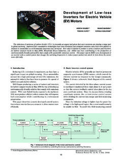
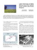
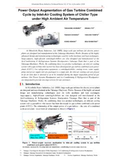
5 This is the first system like this in the world, and it has already been patented or has patents pending in many countries. Mitsubishi Heavy Industries Technical Review Vol. 48 No. 1 (March 2011) 18 |2. Outline of the Super Waste-Heat Recovery Generating system Main Specifications Table 1 shows the specifications of the main diesel engine and the Super Waste-Heat Recovery system for a 7,450 TEU container ship. The Super Waste-Heat Recovery system was designed to operate at maximum efficiency at an ISO 90% of the rateed engine load. Combined Power Train of the Steam and Power Turbines Figure 1 shows the construction of the power train for the steam and power turbines. The power turbine is coupled to the open end (opposite the generator) of the steam turbine shaft through the automatic clutch.
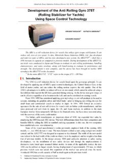
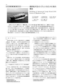
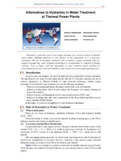
6 The power turbine rotation is reduced by one-stage reduction gears from 20,000 rpm to 8,700 rpm to couple it with the steam turbine. The power turbine and the pinion gear in the reduction gear are connected with a flexible coupling, and the wheel gear in the reduction gear and the steam turbine shaft are coupled with the automatic clutch and flexible coupling. The steam turbine is a condensing axial-flow impulse turbine based on a conventional model, with which MHI has had years of experience in marine use. The power turbine is an adapted Mitsubishi MET turbocharger, with which MHI also has had years of experience. Figure 2 shows an external view of the plant test of the coupled steam and power turbines. The power turbine was driven by steam instead of exhaust gas for facility reasons and was subjected to a load test.
7 The test included automatic clutch engagements/disengagements. Specific items were measured, such as the vibration of each part and the coordination of the power turbine gas valve and the steam turbine speed governor. The test was conducted in the presence of the owner and shipbuilder, and the designed mechanical and electrical generating power performances were verified. Figure 1 Construction of the steam and power turbines Table 1 Specifications of the main diesel engine and Super Waste-Heat Recovery system Main engine output and speed MCR 45,740 kW 78 rpm Steam turbine model Mitsubishi ATD52 CLM Steam turbine maximum output 2,500 kW Steam turbine speed 8,685 rpm Inlet steam pressure and temperature MPa (G), 267 C Degree of vacuum in the condenser kPa Power turbine model Mitsubishi MPT42 Power turbine maximum output 1,700 kW Figure 2 Test operation with combined turbines Power turbine speed 19,414 rpm Generator maximum output and speed 4,000 kW, 1,800 rpm |3.
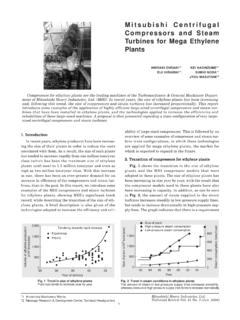
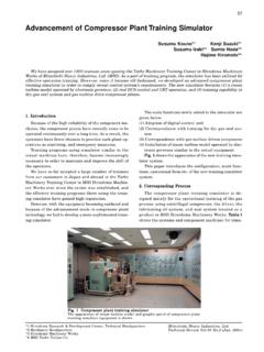
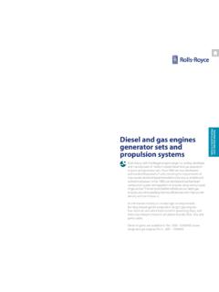
8 Plant Diagram of the Super Waste-Heat Recovery system Figure 3 shows a diagram of the plant. The plant uses a two-stage pressure exhaust-gas economizer. Condensed water at 38 C is sent to the engine jacket cooler, which raises its temperature to approximately 75 C. Then the water is heated up to approximately 135 C by the turbocharger compressor outlet air and sent to the steam separator in the exhaust gas economizer. Mitsubishi Heavy Industries Technical Review Vol. 48 No. 1 (March 2011) 19 Up to 13% of the exhaust gas is extracted from the exhaust manifold and used to drive the power turbine. A bypass valve installed on the exhaust extract line is used to prevent the scavenging pressure from rising suddenly due to the power turbine trip or other factors.
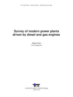
9 During operation, the exhaust gas bypasses the exhaust gas economizer and is released to the air through a duct when the engine load is 30% or lower due to the small amount of energy in the engine exhaust gas. This avoids soot deposits on the economizer tubes from foul exhaust gas. When the power is 35% or higher, the steam turbine starts; at 45%, the power turbine starts. When the total electricity demand of the ship is lower than the capacity of this system , all diesel generators are stopped and the system covers the entire electrical load of the ship, making use of the load optimizing control of the steam and power turbines to obtain the highest level of energy efficiency. Figure 3 Plant diagram |4. Performance and Characteristics of the Super Waste-Heat Recovery system Figure 4 shows the electric power generated by this system under various loads for ISO conditions.
10 When the container ship has many refrigerated containers, a diesel generator operating in parallel is also required. When the number of refrigerated containers is small, this system can be used by itself to supply the ship s electricity. This heat Recovery system may generate more electrical power than the ship requires. If the generator is coupled to the main propulsion shaft, the excessive electric power can be used to assist turning of the shaft to reduce the fuel oil consumption of the main engine. Such a feature has not been requested for the ships ordered to date; therefore, a load control system for the steam and power turbines is instead required. Figure 4 Generated electric power with engine load Mitsubishi Heavy Industries Technical Review Vol. 48 No. 1 (March 2011) 20 The characteristics of this Super Waste-Heat Recovery system including the load control are listed below.