Transcription of DG5S-8 and DG5S-H8 - Eaton
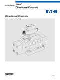
1 Two-Stage, Solenoid Controlled,Pilot Operated, Four-Way Directional Valves591 Revised 11/94DG5S-8 and DG5S-H8 vickers Directional ControlsCross Section of Typical Valve ( DG5S-8 -6B-T-M-U-H5-30)2 IntroductionGeneral DescriptionThe DG5S-8 and DG5S-H8 aretwo-stage directional valves with anintegrally mounted DG4V3(S) (wetarmature solenoid) pilot valves are used to control thedirection of flow in hydraulic directional control in turn providescontrol over the movement of a cylinderor the rotation of a hydraulic and BenefitsDSuitable for the most demandingindustrial applications with dg5s -H8flow capacities up to 530 L/min (140 USgpm) and rated pressure of 310 bar(4500 psi).
2 DAvailable with a wide variety of spooland spring arrangements, stroke andpilot choke adjustments, integral checkvalves, and port vickers DG4V3(S) pilot valve forexceptional responsiveness, durability,and ease of electrical options allow fullcompatibility and easy, reliableconnection in any system response and standard low shockmodels cast body and core passages formaximum strength and minimalpressure solenoids and centeringsprings assure consistent shiftingthrough a wide range of pressure andsilting and backed by vickers , withover 70 years as the global leader influid power and motion of ContentsModel SeriesRecommended FlowMaximum Operating PressurePageDG5S-8To 170 L/min (45 USgpm)210 bar (3000 psi)4DG5S-H8 (High Flow)
3 To 265 L/min (70 USgpm)310 bar (4500 psi)6 Accessories and Weights22 Installation and Application Data24 Response typeX Fast responseBlank Standard low shock modelsSpool control modifications1 Stroke adjustment both ends2 Pilot choke (dual) adjustment3 Pilot choke and stroke adjustment7 Stroke adjustment A port end only8 Stroke adjustment B port end only2-7 Dual pilot choke and strokeadjustment A port end only2-8 Dual pilot choke and strokeadjustment B port end onlyBlank Omit if not requiredPilot pressureE External pilot pressureBlank Internal pilot pressurePilot drainT Internal pilot drainBlank External pilot drainPressure port check valveK 0,35 bar (5 psi) cracking pressureR 3,45 bar (50 psi) cracking pressureS 5,20 bar (75 psi)
4 Cracking pressureBlank Omit if not requiredSpool/Spring arrangementA Spring offset to A portB Spring centered, solenoid AremovedC Spring centeredD Pressure centeredF Spring offset to A port, shiftto centerN No spring detented (pilot only)Left hand assemblyL Left hand, single solenoid if not required. (For right handassembly, P to A port whensolenoid A is energized.)Blank Omit if not requiredManual overrideBlank Plain override solenoidends onlyH Waterproof override solenoidends onlyH2 Waterproof override both ends ofsingle solenoidP2 Plain override both ends of singlesolenoidY Lockable manual overridessolenoid ends only/DC onlyZ No overrides in either endViton sealsF3 For mineral oil & fire resistant fluidsBlank Omit if not requiredSeries designationD Directional control valveG Manifold or subplate mounted5 Solenoid controlled, pilot operatedS Sliding spool, rated pressure210 bar (3000 psi)
5 Interface8 NFPA D08 (ISO 4401-08)Spool typeCode Center position0 Open to T all ports1 Open P & A to T, closed B2 Closed to T all ports3 Closed P & B, open A to T**4 Tandem P to T, closed crossover6 Closed P only, open A & B to T7 Open P to A & B, closed T**8 Tandem P to T, open crossover9 Open to T all ports over tapers11 Open P & B to T, closed A31 Closed P & A, open B to T33 Closed P, open A & B to Tover tapers52 Closed center all portsModel Codes12345678910111234587691012111213141 516171819202122232425** Type 4 and 8 spools may spin within the body causing unusual valve body wear.
6 With this and other spool types, valvemalfunction may occur. Where these applications exist use the DG5S-8 *-30/40 EN470 special designator for 4C/8C anti- Model Series RatingsRecommendedMaximumOperatingPress reM xim m PilotMaximum Tank Line Pressurebar (psi)RecommendedFlow*L/min (USgpm)Pressure(Ports P, A, & B)bar (psi)Maximum PilotPressurebar (psi)External DrainModelsInternal DrainModelsMounting PatternTo 170 (45)210 (3000)210 (3000)210 (3000)210 (3000)ISO 4401-08, NFPA D08(formerly D06), and ANSI flow table see page 8 5 Electrical connections(Code F coil only)T Wired terminal blockPA Instaplug male receptacle onlyPB Instaplug male & female receptaclePA3 Three pin connectorPA5 Five pin connectorBlank Omit if not requiredHousing(Code F coil only)W 1/2 NPT thread wiring housingJ 20 mm thread wiring housingBlank Omit if not requiredElectrical options(Code U coil only)1 ISO with fitted plug6 ISO with fitted plug and lightsSolenoid indicator lights(Code F coil with code T electricalconnections only)
7 L Indicator lightsBlank Omit if not requiredCoil identificationA 110V AC 50 HzB 110V AC 50 Hz/120V AC 60 Hz*C 220V AC 50 HzD 220V AC 50 Hz/240V AC 60 Hz*G 12 VDCH 24 VDCDJ 98 VDCP 110 VDC* For 60 Hz or dual frequencySolenoid energization identityV Solenoid identification determinedby position of solenoid (solenoid Aat port A end and/or solenoid B atport B end)Blank Standard arrangement for (energize solenoid A for flowP to A port)(Code V for any valve with code 4 orcode 8 spool)Flag symbolM Electrical options and featuresSpool indicator switch(Available on models with highperformance pilot DG4V3 only)S3 Normally open (available onvalves with code P* only)S4 Normally closed (available onvalves with code P* only)S5 Free leads (available onvalves with coil type code F only)S6 LVDT type DC switch with Pg7connector plugCoil typeU ISO 4400F Flying leadSP1 Single 6,3 mm spade to IEC 760SP2 Dual 6,3 mm spade to IEC 760 Model Codes (continued)13141516192021 Pilot valve tank pressure rating2 10 bar (145 psi)
8 DG4V3-60 withS3, S4, or S5 spool indicatorswitch5 100 bar (1450 psi) DG4V3S-606 210 bar (3000 psi) DG4V3-60 withAC solenoids and optional S6spool indicator switch7 210 bar (3000 psi) DG4V3-60 withDC solenoids and optional S6spool indicator switchPilot valve port orificesCode Orifice diameter*00 Solid plug*03 0,30 mm ( in)*06 0,60 mm ( in)*08 0,80 mm ( in)*10 1,00 mm ( in)*13 1,30 mm ( in)*15 1,50 mm ( in)*20 2,00 mm ( in)*23 2,30 mm ( in)Blank Omit if not required(* = P, T, A, and/or B as required)Design number30 DG4V3S-60 pilot valve40 DG4V3-60 pilot valve(Subject to change. Installationdimensions same for designs 30 through39 and 40 through 49.)
9 Special Feature2223241817256DG5S-8 Model Series Spring Centering Times atRated Flow and Pressure4 & 8 Shift TimeShift time is defined as the elapsed timefrom when the pilot valve solenoid isenergized to the time the main stagespool shifts to its full stroke. Shift timecurves are shown for standard low shockand fast response models at 210 bar(3000 psi) system pressure with variouspilot pressures and spools. Pressurecentering time curves are shown forpressure centered models. Approximatespring centering times are also listed forspring centered ActionThe pilot valve solenoids of springcentered, pressure centered, and springoffset models must be energizedcontinuously to keep the main stagespool in the shifted position.
10 No-springdetented models only need to beenergized momentarily (forapproximately second).Spring centered and pressure centeredmodels return the valve spool to thecenter position when both solenoids arede-energized or pilot pressure fails orfalls below minimum offset models return the spool tothe offset position by pilot pressure whenthe solenoid is no-spring detented models arede-energized, the pilot and main spoolsremain in their last position as long asthere are no unusual shock, vibration, orpressure transients, and the spool axis ishorizontal. If pilot pressure fails or fallsbelow the minimum, the main spool willspring center (at spring centered flowrates), but will not drift to a reversal offlow position.