Transcription of Diagnostic Repair Manual - Generator Parts
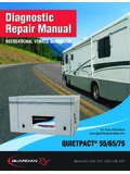
1 DiagnosticRepair ManualDiagnosticRepair ManualFor more 55/65/75 Model 4702, 4703, 4707, 4705, 4706, 4707 recreational vehicle GENERATORSAFETYT hroughout this publication, "DANGER!" and "CAUTION!" blocks are used to alert the mechanic to specialinstructions concerning a particular service or operation that might be hazardous if performed incorrectly orcarelessly. PAY CLOSE ATTENTION TO !! UUNNDDEERR TTHHIISS HHEEAADDIINNGG WWIILLLL BBEE FFOOUUNNDD SSPPEECCIIAALL IINNSSTTRRUUCCTTIIOONNSS WWHHIICCHH,, IIFF NNOOTT CCOOMMPPLLIIEEDDWWIITTHH,, CCOOUULLDD RREESSUULLTT IINN PPEERRSSOONNAALL IINNJJUURRYY OORR !! UUnnddeerr tthhiiss hheeaaddiinngg wwiillll bbee ffoouunndd ssppeecciiaall iinnssttrruuccttiioonnss wwhhiicchh,, iiff nnoott ccoommpplliieedd wwiitthh,, ccoouulldd rreessuulltt iinn ddaamm--aaggee ttoo eeqquuiippmmeenntt aanndd//oorr "Safety Alerts" alone cannot eliminate the hazards that they signal.
2 Strict compliance with these spe-cial Instructions plus "common sense" are major accident prevention TO USERS OF THIS MANUALThis SERVICE Manual has been written and published by Generac to aid our dealers' mechanics and com-pany service personnel when servicing the products described herein. It is assumed that these personnel are familiar with the servicing procedures for these products, or like orsimilar products manufactured and marketed by Generac. That they have been trained in the recommendedservicing procedures for these products, including the use of common hand tools and any special Generactools or tools from other suppliers. Generac could not possibly know of and advise the service trade of all conceivable procedures by which aservice might be performed and of the possible hazards and/or results of each method.
3 We have not under-taken any such wide evaluation. Therefore, anyone who uses a procedure or tool not recommended byGenerac must first satisfy himself that neither his nor the products safety will be endangered by the serviceprocedure information, illustrations and specifications in this Manual are based on the latest product informationavailable at the time of working on these products, remember that the electrical system and engine ignition system are capa-ble of violent and damaging short circuits or severe electrical shocks. If you intend to perform work whereelectrical terminals could be grounded or touched, the battery cables should be disconnected at the time the intake or exhaust openings of the engine are exposed during service, they should be covered toprevent accidental entry of foreign material.
4 Entry of such materials will result in extensive damage when theengine Is any maintenance procedure, replacement fasteners must have the same measurements and strengthas the fasteners that were removed. Metric bolts and nuts have numbers that indicate their bolts use radial lines to indicate strength while most customary nuts do not have strength mark-ings. Mismatched or incorrect fasteners can cause damage, malfunction and possible PARTSC omponents on Generac recreational vehicle generators are designed and manufactured to comply withRecreational vehicle Industry Association (RVIA) Rules and Regulations to minimize the risk of fire or explo-sion. The use of replacement Parts that are not in compliance with such Rules and Regulations could resultin a fire or explosion hazard.
5 When servicing this equipment, It is extremely important that all components beproperly installed and tightened. If Improperly Installed and tightened, sparks could Ignite fuel vapors fromfuel system ooff CCoonntteennttssPage 1 SSAAFFEETTYY ..IINNSSIIDDEE FFRROONNTT CCOOVVEERRSSEECCTTIIOONN 11:: GGEENNEERRAATTOORR FFUUNNDDAAMMEENNTTAALLSS ..33--77 MAGNETISM .. 3 ELECTROMAGNETIC FIELDS .. 3 ELECTROMAGNETIC INDUCTION .. 3A SIMPLE AC Generator .. 4A MORE SOPHISTICATED AC Generator .. 4 FIELD BOOST .. 6 Generator AC CONNECTION SYSTEM .. 6 SSEECCTTIIOONN 22:: MMAAJJOORR GGEENNEERRAATTOORR ASSEMBLY .. 8 STATOR ASSEMBLY .. 8 BRUSH HOLDER .. 9 BATTERY CHARGE COMPONENTS .. 9 EXCITATION CIRCUIT COMPONENTS .. 9 CRANKCASE BREATHER .. 10 SSEECCTTIIOONN 33:: IINNSSUULLAATTIIOONN RREESSIISSTTAANNCCEE TTEESSTTSS.
6 1122--1144 EFFECTS OF DIRT AND MOISTURE .. 12 INSULATION RESISTANCE TESTERS .. 12 DRYING THE Generator .. 12 CLEANING THE Generator .. 12 STATOR INSULATION RESISTANCE .. 13 TESTING ROTOR INSULATION .. 14 THE MEGOHMMETER .. 14 SSEECCTTIIOONN 44:: MMEEAASSUURRIINNGG EELLEECCTTRRIICCIITTYY ..1155--1177 METERS .. 15 THE VOM .. 15 MEASURING AC VOLTAGE .. 15 MEASURING DC VOLTAGE .. 15 MEASURING AC FREQUENCY .. 16 MEASURING CURRENT .. 16 MEASURING RESISTANCE .. 16 ELECTRICAL UNITS .. 17 OHM S LAW .. 17 SSEECCTTIIOONN 55::EENNGGIINNEE DDCC CCOONNTTRROOLL SSYYSSTTEEMM ..1188--2266 INTRODUCTION .. 18 OPERATIONAL ANALYSIS .. 18-23 ENGINE CONTROLLER CIRCUIT BOARD .. 24 BATTERY .. AMP FUSE .. 25 FUEL PRIMER SWITCH .. 25 START-STOP SWITCH.
7 25 STARTER CONTACTOR RELAY& STARTER MOTOR .. 26 SSEECCTTIIOONN 66:: TTRROOUUBBLLEESSHHOOOOTTIINNGG FFLLOOWWCCHHAARRTTSS ..2277--3377IF PROBLEM INVOLVES AC OUTPUT .. 27 PROBLEM 1 - VOLTAGE & FREQUENCY ARE BOTH HIGH OR LOW .. 27 PROBLEM 2 - Generator PRODUCES ZERO VOLTAGE OR RESIDUAL VOLTAGE (5-12 VAC) .. 28-29 PROBLEM 3 - NO BATTERY CHARGE OUTPUT .. 29 PROBLEM 4 - EXCESSIVE VOLTAGE/FREQUENCY DROOP WHEN LOAD IS APPLIED .. 30 PROBLEM 5 - PRIMING FUNCTION DOES NOT WORK(GASOLINE MODELS) .. 30 PROBLEM 6 - ENGINE WILL NOT CRANK .. 31 PROBLEM 7 - ENGINE CRANKS BUT WILL NOT START(GASOLINE UNITS) .. 32 PROBLEM 7 - ENGINE CRANKS BUT WILL NOT START(LP UNITS) .. 33 PROBLEM 8 - ENGINE STARTS HARD AND RUNS ROUGH(GASOLINE UNITS) .. 34 PROBLEM 8 - ENGINE STARTS HARD AND RUNS ROUGH(LP UNITS).
8 34 PROBLEM 9 - ENGINE STARTS THEN SHUTS DOWN .. 36 PROBLEM 10 - AMP (F1) FUSE BLOWING .. 37 SSEECCTTIIOONN 77:: DDIIAAGGNNOOSSTTIICC .. 38 TEST 1 - Check No-Load Voltage And Frequency .. 38 TEST 2 - Check Engine Governor .. 38 TEST 3 - Test Excitation Circuit Breaker .. 39 TEST 4 - Fixed Excitation Test/Rotor Amp Draw .. 39 TEST 5 - Wire Continuity .. 40 TEST 6 - Check Field Boost .. 41 TEST 7 - Test Stator DPE 41 TEST 8 - Check Sensing Leads/Power Windings .. 42 TEST 9 - Check Brush Leads .. 43 TEST 10 - Check Brushes & Slip Rings .. 43 TEST 11 - Check Rotor Assembly .. 44 TEST 12 - Check Main Circuit Breaker .. 44 TEST 13 - Check Load Voltage & Frequency .. 45 TEST 14 - Check Load Watts & Amperage .. 45 TEST 15 - Check Battery Charge Output.
9 45 TEST 16 - Check Battery Charge Rectifier .. 45 TEST 17 - Check Battery Charge Windings/Battery Charge Resistor .. 46 TEST 18 - Try Cranking the Engine .. 47 TEST 19 - Test Primer 47 TEST 20 - Check Fuel Pump .. 48 TEST 21 - Check Amp Fuse .. 49 TEST 22 - Check Battery & 49 TEST 23 - Check Power Supply to Circuit Board .. 49 TEST 24 - Check Start-Stop Switch .. 50 TEST 25 - Check Power Supply to Wire 56 .. 51 TEST 26 - Check Starter Contactor Relay .. 51 TEST 26A - Check Starter Contactor .. 52 TEST 27 - Check Starter Motor .. 52 TEST 28 - Check Fuel 54 TEST 29 - Check Wire 14 Power Supply .. 56 TEST 30 - Check Wire 18 .. 56 TEST 31 - Check Fuel Solenoid(Gasoline Models) .. 57 TEST 32 - Check Ignition Spark .. 57 TEST 33 - Check Spark Plugs .. 59 TEST 34 - Check and Adjust Ignition Magnetos.
10 59 TEST 35 - Check Valve Adjustment .. 61 TEST 36 - Check Carburetion .. 62 TEST 37 - Check Choke Solenoid .. 62 TEST 38 - Check Engine / Cylinder Leak Down Test /Compression Test .. 64 TEST 39 - Check Oil Pressure Switch .. 65 TEST 40 - Test Oil Temperature Switch .. 65 TEST 41 - Test Choke Heater .. 66 TEST 42 - Check LPG Fuel Solenoid .. 66 SSEECCTTIIOONN 88:: DISASSEMBLY .. 68 Enclosure/Panel Removal ..68 Stator Removal .. 68 Rotor Removal .. 68 Belt Tensioning .. 69 Engine Removal .. 69 Startor Removal .. 69 Flywheel/Magneto Removal .. 70 SSEECCTTIIOONN 99::EEXXPPLLOODDEEDD VVIIEEWWSS // PPAARRTT & PULLEY DRAWING .. 72 ENCLOSURE DRAWING .. 74 SHEET METAL DRAWING .. 76 CONTROL PANEL DRAWING .. 78760 V-TWIN ENGINE DRAWING .. 80LP REGULATOR DRAWING.

