Transcription of DIAGNOSTIC SERVICE MANUAL - RV Tech Library
1 1 DIAGNOSTICSERVICE MANUALForm No. 11/02 2002 Dometic CorporationLaGrange, IN 467612 ContentsPAGE & Oasis Elite 3 SECTION 1- Wiring .. Supply From Control Box To Inside Hardware Channel (WeatherPro Only) .. Connection & Motor .. To Remote Switch .. Sensor Cable .. Interlock wire .. 5 SECTION 2- WeatherPro Wind Sensor .. Sensor .. 6 SECTION 3- Control Box .. Board .. Box Rocker Switch .. Sensor Toggle Switch .. 6-7 SECTION 4- Remote Switch .. Switch .. 7 SECTION 5- Remote Key FOB .. Key FOB .. 8 SECTION 6- WeatherPro Auxiliary Cable .. 8 SECTION 7- WeatherPro Emergency Retract Retract Procedure ..8-9 SECTION 8- WeatherPro Fabric, Roller Tube, Torsion Assembly& Weathershield Replacement .. Removal.
2 Hand Torsion Hand Drive Assembly Removal .. Removal From Roller Tube .. Assembly Removal And Replacement .. Fabric On Roller Assembly Replacement .. Hand Torsion Assembly Winding .. 13 SECTION 9- Wiring Diagram .. 143 SYMPTONCAUSELOCATION1. Awning will not open1. 12 VDC Supply WireSection FuseSection Ignition Interlock (WeatherPro)Section & Wiring/ConnectionsSection , , , & Wind (WeatherPro)Section & Circuit Board WiringSection MotorSection Awning will not close1. 12 VDC Supply WireSection FuseSection Wiring/ConnectionsSection , , , , & Circuit Board WiringSection MotorSection Awning works with remote switch1. DistanceSection not key FOB (WeatherPro Only)2. Key FOB BatterySection Key FOB ProgrammingSection Awning works with key FOB but not1.
3 Circuit Board WiringSection & switch (WeatherPro Only)2. SwitchSection Awning will open when ignition key is on position (WeatherPro Only)2. Circuit BoardSection Awning works in opposite direction1. Wiring/ConnectionsSection Circuit Board WiringSection & SwitchSection & WeatherPro awning works when Oasis1. Wiring/ConnectionsSection & should or visa versa2. Circuit Board WiringSection Awning does not close during high wind1. Wind Sensor Switch OffSection Wind Sensor WiringSection & Wind SensorSection Beeping sound coming from control box1. Wind Sensor WiringSection (WeatherPro Only)2. Wind SensorSection Auxiliary Close/Open awning1. No 12 VDC in RVSection (WeatherPro Only)11. Emergency Close Awning1.
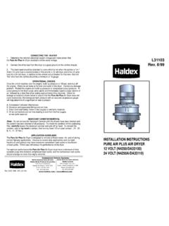
4 No 12 VDC AvailableSection (WeatherPro Only)2. Awning InoperableSection Fabric, Roller Tube, Torsion AssemblySection Weathershield Replacement(WeatherPro Only)4 SECTION 1 Supply The 12 VDC supply wire must be run fromthe 12 VDC supply source to the ControlBox. It is recommended that these wiresbe RED+ and Black 12 gauge wires. Thisneeds to be on a separate 15 amp FIG. To ensure proper operation, the controlbox must have a minimum of VDC atthe control box during operation. Checkvoltage output on the Red and Black wireat the control box. If voltage is below ,check voltage at supply, If OK it may benecessary to increase the wire size goingto the control box. See FIG. Wire From Control Box to Awning. Arm As-sembly (WeatherPro) and Awning Motor (Oa-sis Elite)A Red and Black Wire (WeatherPro) Red/Whiteand Blue wire (Oasis Elite) of adequate size mustbe run between the control box and the avoid voltage drop follow the chart below todetermining the proper size wire to be LengthWire Size10' & Under14 Gauge11' to 30'12 GaugeOver 30'10 GaugeEXTENDRETRACTA wningControlFUSE INSIDEW eatherProMain ArmRight SidePig Tail toControl BoxEndPig Tailfor MotorOasis EliteMotorBlackRedRedBlackRed/WhiteBlueB lackRedBlueRedFIG.
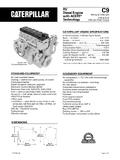
5 Wire Inside Hardware Channel (WeatherPro Only)To make the connection between the wire run and the awning motor there is a cable run inthe hardware from the bottom to the top. Checkthis wire for pinches or breaks. If wire is defec-tive replace with new Motor Connection & awning motor is connected to thehardware at the top of the awning hard-ware front channel. Make sure connec-tion is tight and corrosion Disconnect the motor from the hardwareconnection. See FIG. Apply DC volt-age directly to the motor wire minimum of VDC is required to op-erate the motor. If motor does not turn it isdefective and the drive assembly must + INSIDE12 VDCP ower Supply15 AMPB reakerRed +Black-FIG. Ignition Interlock WireThe ignition Interlock wire when correctly installedwill prevent the awning from opening when theignition key is in the on position.
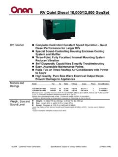
6 This wire is routedbetween the ignition isolator (Pink) wire of thecontrol box to the ignition isolator of the should be a 16 gauge wire. Make sure wireconnections are tight and corrosion To Remote SwitchThe remote switch is connected to the controlbox with three (3) 16 gauge wires. These areBrown, Yellow, Green for WeatherPro and Brown/White, Yellow/White, Green/White for Oasis switch end of the wire will be connected tothe switch by means of 1/4" insulated tab con-nectors. The control box end has a pig tail toconnect the control box to these three wires. Seeswitch for correct wiring. Make sure connectionsare tight and corrosion Wind Sensor CableThe wind sensor is connected to the control boxwith a FLAT four (4) conductor cable terminatedon both ends with an RJ-11 telephone connec-tor.
7 Maximum length is 18'. This cable is polaritysensitive and must be assembled as shown. Astandard telephone cable will not work. Cablecan be checked with a Dometic tester. If cable is found to be defective re-place with a cable no longer than 18'EXTENDRETRACTA wningControlFUSE INSIDEW eatherProRemoteSwitchEXTENDRETRACTPig Tail toRemote SwitchOasis EliteRemoteSwitchBrown/WhiteGreen/ WhiteYellow/WhiteGreenYellowBrownGreenYe llowBrownEXTENDRETRACTB rownWhiteGreen/ WhiteYellow/WhitePig Tail toRemote SwitchFIG. ConductorFLAT CableConnectionsBlackGreenYellowBlackGre enPin 1RJ-11 ConnectorFlat Four Conductor CableFIG. INSIDE+IgnitionIsolatorPinkFIG. 2 Wind wind sensor monitors the wind speed andsends a signal to the control box if wind speedsexceeds the preset setting.
8 The correct positionof the winds sensor is critical. It shoud be within3 feet of the right side top mounting bracket andaway from other objects. To check out the windsensor, extend the awning and place the windsensor switch in the ENABLE (ON) position. Youcan create sufficient amount of wind by placing astandard hair dryer approximately 6 inches awayfrom the wind sensor with the dryer set on HIGHand NO HEAT. The awning should close VDCS upplyWind Sensor SwitchENABLE (ON)DISABLE (OFF)Red/WhiteBlueBlack 12 VDC -Red 12 VDC +T1T2T3T4T5T6T7T8T915 AMPFUSET10T11 T12T13T14T15 T16T17T18T19T20 EXTENDRETRACTB rown WhiteGreen/WhiteYellow/WhiteGreenBrownYe llowBlueBluePinkGreenYellowBrownRedBlack Cable to Wind Sensor(18 Foot Maximum)WeatherProOutputOasis EliteOutputOasis EliteRemoteSwitchWeatherProRocker SwitchWeatherProRemoteSwitchSECTION 3 Control BoxThe control box is the heart of the system andcontains a fuse, rocker switch, wind sensor toggleswitch & circuit Circuit BoardThe circuit board can be checked out by the pro-cess of elimination.
9 Make sure there is VDCgoing into the circuit Disconnect all pig tails coming out of thecontrol Check for VDC (minimum) at T1 (red+) and T3 (black ) on circuit Check for VDC (minimum) on eachleg of fuse. Place the negative lead of thevolt meter on T3 and check each leg ofthe fuse with the positive lead. This shouldread VDC on each leg. Replace Check for voltage at the WeatherPro out-put pigtail (Red & Black wire). First, pressand hold the rocker switch in the extendposition. Place the negative lead of thedigital volt meter on the Black wire posi-tion of the pigtail and the positive lead ofthe volt meter on the Red wire position ofthe pigtail. The meter should read ( )negative VDC (minimum).
10 Do notmove the volt meter leads and press andhold the rocker switch in the retract posi-tion. The meter should read (+) VDC (minimum).FIG. Sensor SwitchControl BoxWind SensorENABLEDISABLEWind To check the WeatherPro remote switchconnection (Brown, Green, & Yellow) wireuse a jumper wire and connect the Yellowto Brown. You should hear the relay connect the Green to Brown and youshould hear another Check the Oasis Elite remote switch wireand the output wire at the same time. Theremote switch wires are Brown/White,Green/White and Yellow/White. The out-put wire is Red/White and Blue. Connectthe positive lead of the digital volt meterto the Red/White wire position of the pig-tail and the negative to the Blue wire po-sition of the pigtail.