Transcription of DIAGNOSTICS – HYBRID CONTROL SYSTEM DTC …
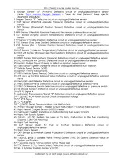
1 05 772 DIAGNOSTICSHYBRID CONTROL SYSTEM936 Author :Date :2004 Prius Preliminary Release (RM1075U)DTCP2122/104 THROTTLE/PEDAL POSITIONSENSOR/SWITCH D CIRCUIT LOW INPUTDTCP2123/105 THROTTLE/PEDAL POSITIONSENSOR/SWITCH D CIRCUIT HIGH INPUTDTCP2127/107 THROTTLE/PEDAL POSITIONSENSOR/SWITCH E CIRCUIT LOW INPUTDTCP2128/108 THROTTLE/PEDAL POSITIONSENSOR/SWITCH E CIRCUIT HIGH INPUTHINT:This is the repair procedure for the accelerator pedal position DESCRIPTIONHINT: This electrical throttle SYSTEM does not use a throttle cable. This accelerator pedal position sensor is a non contact accelerator pedal position sensor is mounted on the accelerator pedal to detect how much it is de-pressed. It has 2 sensor terminals (VPA and VPA2) to detect the accelerator pedal position and a malfunctionof the accelerator pedal position sensor itself.
2 Since this sensor is electronically controlled with hall elements,accurate CONTROL and reliability can be the accelerator pedal position sensor, the voltage applied to terminals VPA and VPA2 of the HV controlECU changes between 0 V and 5 V in proportion to the degree of depressing the accelerator pedal. TheVPA is a signal to indicate the actual accelerator pedal position angle which is used for the HV SYSTEM CONTROL ,and the VPA2 is a signal to indicate the actual accelerator pedal position angle which is used for detectinga malfunction of the sensor itself (terminal VPA).The HV CONTROL ECU judges how much the accelerator pedal is being depressed from the VPA and VPA2signals, and controls the HV SYSTEM based on the 01A19694A19803 Accelerator Pedal Position SensorHV CONTROL ECUM agnetMagnetIC Pedal Position Sensor Output Voltage (V)Usable RangeAccelerator Pedal Position Angle (deg)*1*2 Accelerator Pedal ReleasedAccelerator Pedal Fully *1:*2:5 V5 V DIAGNOSTICSHYBRID CONTROL SYSTEM05 773937 Author :Date.
3 2004 Prius Preliminary Release (RM1075U)DTC CodeDTC Detection ConditionTrouble AreaP2122104 Open or GND short in accelerator pedal positionmain sensor circuit Wire harness or connector Accelerator pedal rod assembly HV CONTROL ECUP2123105+B short in accelerator pedal position main sensorcircuit Wire harness or connector Accelerator pedal rod assembly HV CONTROL ECUP2127107 Open or GND short in accelerator pedal positionsub sensor circuit Wire harness or connector Accelerator pedal rod assembly HV CONTROL ECUP2128108+B short in accelerator pedal position sub sensorcircuit Wire harness or connector Accelerator pedal rod assembly HV CONTROL ECUA92108A13 Accelerator Pedal Position Sensor(Shielded)HV CONTROL ECUH16 EPAEP2 VCP2 VPA2 VPAVCPAEP1EP2 VCP2 VPA2 VCP1 VPA1 IKJ5J/CALBYWRG521346H16H16H16H16H1626272 5343533FI7052 DepressedReleased05 774 DIAGNOSTICSHYBRID CONTROL SYSTEM938 Author :Date :2004 Prius Preliminary Release (RM1075U)WIRING DIAGRAMINSPECTION PROCEDURE1 READ VALUE OF HAND HELD TESTER(ACCEL POS #1 AND #2)(a)Connect the hand held tester to the DLC3.
4 (b)Turn the power switch ON (IG).(c)Turn the hand held tester ON.(d)On the hand held tester, enter the following menus:DIAGNOSIS / ENHANCED OBD II / HV ECU / DATA LIST.(e)Read the ACCEL POS #1 and #2 values on the hand held tester with the engine : Changes with accelerator pedal pressureOKGo to step 5 NGA65745HV CONTROL ECU ConnectorH16 VCP1 VCP2 VPA2EP2EP1 VPA1A92050 Wire Harness Side:Accelerator Pedal PositionSensor ConnectorVCP2A13 Front ViewVPAEP2 EPAVPA2 VCPA DIAGNOSTICSHYBRID CONTROL SYSTEM05 775939 Author :Date :2004 Prius Preliminary Release (RM1075U)2 CHECK HARNESS AND CONNECTOR( HYBRID VEHICLE CONTROL ECU ACCELERATOR PEDAL POSITION SENSOR)(a)Disconnect the H16 HV CONTROL ECU connector.(b)Disconnect the A13 accelerator pedal position sensorconnector.
5 (c)Turn the power switch ON (IG).(d)Measure the voltage between the terminals of the HVcontrol ECU connector and body :Tester ConnectionSpecified ConditionVPA1 (H16 26) Body groundBelow 1 VVCP1 (H16 25) Body groundBelow 1 VEP1 (H16 27) Body groundBelow 1 VVPA2 (H16 34) Body groundBelow 1 VVCP2 (H16 33) Body groundBelow 1 VEP2 (H16 35) Body groundBelow 1 V(e)Turn the power switch OFF.(f)Check the resistance between the wire harness side (Check for open):Tester ConnectionSpecified ConditionVPA1 (H16 26) VPA (A13 6)Below 1 VCP1 (H16 25) VCPA (A13 4)Below 1 EP1 (H16 27) EPA (A13 5)Below 1 VPA2 (H16 34) VPA2 (A13 3)Below 1 VCP2 (H16 33) VCP2 (A13 1)Below 1 EP2 (H16 35) EP2 (A13 2)Below 1 Standard (Check for short).
6 Tester ConnectionSpecified ConditionVPA1 (H16 26) or VPA (A13 6) Body ground10 k or higherVCP1 (H16 25) or VCPA (A13 4) Body ground10 k or higherEP1 (H16 27) or EPA (A13 5) Body ground10 k or higherVPA2 (H16 34) or VPA2 (A13 3) Body ground10 k or higherVCP2 (H16 33) or VCP2 (A13 1) Body ground10 k or higherEP2 (H16 35) or EP2 (A13 2) Body ground10 k or higher(g)Reconnect the accelerator pedal position sensor connec-tor.(h)Reconnect the HV CONTROL ECU OR REPLACE HARNESS ORCONNECTOROKA92051 Accelerator PedalPosition Sensor ConnectorA18294HV CONTROL ECU ConnectorH16EP2 VCP2EP1 VCP105 776 DIAGNOSTICSHYBRID CONTROL SYSTEM940 Author :Date :2004 Prius Preliminary Release (RM1075U)3 INSPECT HYBRID VEHICLE CONTROL ECU(VCP1 OR VCP2 VOLTAGE)(a)Disconnect the A13 accelerator pedal position sensorconnector.
7 (b)Turn the power switch ON (IG).(c)Measure the voltage between the terminals of the HVcontrol ECU :Tester ConnectionSpecified ConditionVCP1 (H16 25) EP1 (H16 27) to VVCP2 (H16 33) EP2 (H16 35) to V(d)Reconnect the accelerator pedal position sensor HYBRID VEHICLE CONTROL ECU(See page 21 124)OK4 REPLACE ACCELERATOR PEDAL ROD ASSY (See page 21 128)GO5 CHECK IF DTC OUTPUT RECURS(DTC P2122, P2123, P2127 OR P2128)(a)Connect the hand held tester to the DLC3.(b)Turn the power switch ON (IG).(c)Turn the hand held tester ON.(d)On the hand held tester, enter the following menus: DIAGNOSIS / ENHANCED OBD II / HV ECU /DTC INFO / TROUBLE CODES.(e)Perform a simulation test.(f)Read : DTC P2122, P2123, P2127 or P2128 is not output againYESSYSTEM OKNOREPLACE HYBRID VEHICLE CONTROL ECU (See page 21 124)