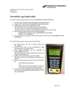
Transcription of Diagnostics - Wireless Telemetry
1 ACH550-UH User s Manual1-281 DiagnosticsDiagnosticsWarning! Do not attempt any measurement, parts replacement or other service procedure not described in this manual. Such action will void the warranty, may endanger correct operation, and increase downtime and ! All electrical installation and maintenance work described in this chapter should only be undertaken by qualified service personnel. The Safety instructions on the first pages of this manual must be displaysThe drive detects error situations and reports them using: The green and red LED on the body of the drive The status LED on the control panel (if the HVAC control panel is attached to the drive) The control panel display (if the HVAC control panel is attached to the drive) The Fault Word and Alarm Word parameter bits (parameters 0305 to 0309).
2 See Group 03: ACTUAL SIGNALS on page form of the display depends on the severity of the error. You can specify the severity for many errors by directing the drive to: Ignore the error situation. Report the situation as an alarm. Report the situation as a fault. Red faultsThe drive signals that it has detected a severe error, or fault, by: Enabling the red LED on the drive (LED is either steady on or blinking). Setting an appropriate bit in a Fault Word parameter (0305 to 0307). Overriding the control panel display with the display of a fault code.
3 Stopping the motor (if it was on).The fault code on the control panel display is temporary. Pressing any of the following buttons removes the fault message: MENU, ENTER, UP button or DOWN button. The message reappears after a few seconds if the control panel is not touched and the fault is still User s ManualDiagnosticsFlashing green alarmsFor less severe errors, called alarms, the diagnostic display is advisory. For these situations, the drive is simply reporting that it had detected something unusual. In these situations, the drive: Flashes the green LED on the drive (does not apply to alarms that arise from control panel operation errors).
4 Sets an appropriate bit in an Alarm Word parameter (0308 or 0309). See Group 03: ACTUAL SIGNALS on page 1-87 for the bit definitions. Overrides the control panel display with the display of an alarm code and/or messages disappear from the control panel display after a few seconds. The message returns periodically as long as the alarm condition exists. Correcting faultsThe recommended corrective action for faults is: Use the Fault listing table below to find and address the root cause of the problem. Reset the drive. See Fault resetting on page listingFault CodeFault Name In PanelDescription and Recommended Corrective Action1 OVERCURRENTO utput current is excessive.
5 Check for and correct: Excessive motor load. Insufficient acceleration time (parameters 2202 ACCELER TIME 1 and 2205 ACCELER TIME 2). Faulty motor, motor cables or OVERVOLT Intermediate circuit DC voltage is excessive. Check for and correct: Static or transient overvoltages in the input power supply. Insufficient deceleration time (parameters 2203 DECELER TIME 1 and 2206 DECELER TIME 2). Verify that overvoltage controller is ON (using parameter 2005).3 DEV OVERTEMP Drive heatsink is overheated. Temperature is at or above & R7/R8: 115 C (239 F)R5/R6: 125 C (257 F) Check for and correct: Fan failure.
6 Obstructions in the air flow. Dirt or dust coating on the heat sink. Excessive ambient temperature. Excessive motor CIRCF ault current. Check for and correct: A short-circuit in the motor cable(s) or motor. Supply User s Manual1-283 Diagnostics5 RESERVEDNot UNDERVOLTI ntermediate circuit DC voltage is not sufficient. Check for and correct: Missing phase in the input power supply. Blown fuse. Undervoltage on LOSS Analog input 1 loss. Analog input value is less than AI1 FLT LIMIT (3021). Check for and correct: Source and connection for analog input.
7 Parameter settings for AI1 FLT LIMIT (3021) and 3001AI<MIN LOSS Analog input 2 loss. Analog input value is less than AI2 FLT LIMIT (3022). Check for and correct: Source and connection for analog input. Parameter settings for AI2 FLT LIMIT (3022) and 3001AI<MIN TEMPM otor is too hot, based on either the drive s estimate or on temperature feedback. Check for overloaded motor. Adjust the parameters used for the estimate ( ). Check the temperature sensors and Group 35 LOSS Panel communication is lost and either: Drive is in local control mode (the control panel displays HAND or OFF), or Drive is in remote control mode (AUTO) and is parameterized to accept start/stop, direction or reference from the control panel.
8 To correct check: Communication lines and connections Parameter 3002 PANEL COMM ERROR. Parameters in Group 10: START/STOP/DIR and Group 11: REFERENCE SELECT (if drive operation is AUTO).11ID RUN FAIL The motor ID run was not completed successfully. Check for and correct: Motor connections Motor parameters STALL Motor or process stall. Motor is operating in the stall region. Check for and correct: Excessive load. Insufficient motor power. Parameters FLT 1 Digital input defined to report first external fault is active. See parameter 3003 EXTERNAL FAULT FLT 2 Digital input defined to report second external fault is active.
9 See parameter 3004 EXTERNAL FAULT CodeFault Name In PanelDescription and Recommended Corrective Action1-284 ACH550-UH User s ManualDiagnostics16 EARTH FAULTP ossible ground fault detected in the motor or motor cables. The drive monitors for ground faults while the drive is running and while the drive is not running. Detection is more sensitive when the drive is not running and can produce false corrections: Check for/correct faults in the input wiring. Verify that motor cable does not exceed maximum specified length. A delta grounded input power supply and motor cables with high capacitance may result in erroneous error reports during non-running tests.
10 To disable response to fault monitoring when the drive is not running, use parameter 3023 WIRING FAULT. To disable response to all ground fault monitoring, use parameter 3017 EARTH Motor load is lower than expected. Check for and correct: Disconnected load. Group 37: USER LOAD FAIL Internal fault. The thermistor measuring the internal temperature of the drive is open or shorted. Contact your local ABB sales LINK Internal fault. A communication-related problem has been detected on the fiber optic link between the OITF and OINT boards. Contact your local ABB sales representative.


