Transcription of DIGITAL ANNUNCIATOR INSTALLATION …
1 DIGITAL ANNUNCIATOR INSTALLATION instructions . DD-40 NTS-O, DD-40 NTS-U DD-NTS II 5-02. WARNING: READ THESE instructions CAREFULLY BEFORE INSTALLING OR. OPERATING THE DD ANNUNCIATOR SYSTEM. AN IMPROPERLY INSTALLED OR. OPERATING DEVICE MAY RESULT IN AN UNSAFE OPERATING CONDITION OF THE. MONITORED MACHINE WHICH CONSEQUENTLY COULD POSE THE THREAT OF. PERSONAL INJURY TO OPERATORS OR OTHER NEARBY PERSONNEL. DESCRIPTION. The Altronic DD-40 NTS DIGITAL ANNUNCIATOR is an electronic, 40-point monitor and shutdown device. The ANNUNCIATOR has a built-in hourmeter / tachometer with over speed protection. A front mounted keypad serves as a user interface along with a LCD display. The DD-40 NTS ANNUNCIATOR system is suitable for use in Class I, Group C or D, Division 2. hazardous locations and consists of the following items: DD-40 NTS-O ANNUNCIATOR , 40 normally open points DD-40 NTS-U ANNUNCIATOR , 40 normally closed or open points (can be mixed).
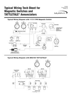
2 (requires terminal module part no. 672169-1). 691200-1 Power Supply - 10 to 30 Vdc, 50 mA max. or 100 to 400 volt negative ground CD ignition systems. 693115-1 Cable, DB-25 (2 required for DD-40 NTS-U unit only). 693116-1 Cable, DB-9 (for RS-232 serial communications). RS-232 / RS-485 serial communications are provided for remote engine monitoring via modem or satellite. Serial communications require the use of the DC power option. For reliable operation, the following instructions must be adhered to strictly. MOUNTING. ANNUNCIATOR UNIT - Using four #10 screws, mount the ANNUNCIATOR Unit inside a control panel or to a suitable flat surface so that the display is at a convenient viewing height. A. drilling template is provided. The ANNUNCIATOR unit box must be grounded. NOTE: Avoid mounting with the LCD display facing direct sunlight.
3 The display temperature range is -40 F. to +175 F. 691200-1 POWER SUPPLY - The Power Supply mounts directly to the back of the ANNUNCIATOR Unit using two 8-32 x 5/16" length screws provided. The terminal strip board (only applicable on the -U version) can be snapped on 32 or 35 mm DIN mounting rails. -1- WIRING (SEE WIRING DIAGRAMS). The ANNUNCIATOR unit plugs into the power supply through a DB-9 connector. The sensor leads connect to the removable terminal strips on the back of the ANNUNCIATOR . These terminal strips match those used with the earlier DD-40NT / DD-20NT systems. At the terminal strip of the ANNUNCIATOR unit, strip the insulation back 3/8"; twist the exposed wires tightly together. Insert the exposed wire end completely into the terminal strip and securely tighten the clamping screw. It is suggested that wire 18 AWG (max.)
4 To 24 AWG. (min.) be used for the connections directly to the ANNUNCIATOR terminal strip connector. Wires running to the various sensors should be in good condition or replaced with new wiring. Terminations to the main panel terminal strip (if used) should be made with a suitable terminal and crimping tool or by soldering. There is no requirement for explosion-proof conduit or Class I enclosures; however, suitable physical protection should be provided. CAUTION: a.) SENSOR WIRING: Sensor wires within the panel enclosure must be kept at least two (2) inches from other wiring. Use a separate junction box for ignition and fuel valve wires. Run sensor leads leaving the panel in a conduit separate from all other wiring and keep separate throughout the INSTALLATION . Wiring to the sensors must have a grade of insulation capable of withstanding an AC voltage of 500 V.
5 RMS. Sensor leads may be connected to any passive device using contacts such as standard switch gauges or level switches. DO NOT connect sensor leads to relay contacts or to any voltage producing element. b.) Sensors will be exposed to much lower voltages and current than with the standard Murphy tattletale or similar type system. In the case of a field conversion where sensors have previously been used with Murphy tattletales, it is recommended that the sensors be checked frequently when the DD system is first put into use. Sensor contacts may be burned or pitted from past exposure to ignition system primary voltage. It is advisable to replace such sensors. c.) If it becomes necessary to check sensor to panel wiring with an ohmmeter or other checker, first DISCONNECT the plug-in terminal strips from the back of the ANNUNCIATOR Unit.
6 Applying voltage to the ANNUNCIATOR through the sensor leads may damage the device. In addition, the area should be tested as non-hazardous before such testing commences. For the -U version, connect the ANNUNCIATOR unit to the 672169-1 terminal modules using 693115-x cables with standard DB-25 connectors. Make sure the cables are securely connected. WARNING REGARDING OLDER ALTRONIC OVERSPEED DEVICES: If retrofitting into an older panel, the DD-40 NTS ANNUNCIATOR will not recognize the output signal from older Altronic overspeed devices: DTO-1000, DTO-1010, DTO-2200, DTO-3200. DTHO-2100, DO-3300, PTO-2100, PTHO-2100. These devices will NOT work for overspeed protection in conjunction with a DD-40 NTS. ANNUNCIATOR . For such protection, use the overspeed feature built into the DD-40 NTS. ANNUNCIATOR (refer to section ).
7 -2- ANNUNCIATOR CONFIGURATION. The DD-40 NTS series unit MUST be configured prior to use. If replacing an older series DD. series ANNUNCIATOR , modes 1 and 4 can be used to directly emulate the older system's performance. Mode 1 duplicates the operation of the DD-40 series and mode 4 duplicates the DD-20 series units. To configure the unit, press the MENU key to reach the configuration headings from the normal display mode. After a selection has been made, press the ENTER. key to save the selection. Press MENU to move to the next step. A flowchart is provided that shows step-by-step progression through the ANNUNCIATOR configuration procedure. CONFIGURE MODE - The mode selection allows the unit to be programmed in one of four modes as shown. The RESET button must be pressed after a change in mode number.
8 NOTE: A keypad sequence (password) is required to edit values. From the status screen (RPM, HOURS, or STATUS) , press and hold down the ENTER key then press the MENU key at the same time to allow values to be modified. Otherwise, selected items may only be viewed. There is no similar protection for the TIMER button (Class B1 and B2 timers) or hourmeter. MODE TYPE OF POINTS CHANNELS NOTES. 24 Class A 30-37, 40-47, 50-57 Duplicates operation 1 of DD-40NT series. 16 Class B1 10-17, 20-27. 24 Class A 30-37, 40-47, 50-57. 2 12 Class B1 10-17, 20-23. 4 Class B2 24-27. 24 Class A 30-37, 40-47, 50-57. 10 Class B1 10-17, 20-21. 3. 2 Class B2 22-23. 4 Class C 24-27. 12 Class A 20-27, 30-32, 40 Duplicates operation 4 of DD-20NT series. 8 Class B1 10-17. Class Definitions: Class A Point is always armed. Class B1 Point is armed B1 time after power-up or pressing the RESET key.
9 Class B2 Point is armed B2 time after power-up or pressing the RESET key. Class C Point is armed after it clears. Use the UP and DOWN keys to select the mode and press the ENTER key to save the mode. PROGRAM RPM 1 - This selects the RPM pre-divide number equal to the pulses per revolution (PPR). The RPM signal can be from either a CD ignition shutdown lead or a magnetic pickup. The range is selectable from to 360 PPR. Use the UP and DOWN keys to select the proper pre-divide number and press the ENTER key to save. -3- PROGRAM RPM 2 - This selects the RPM overspeed value. The range is selectable from 1 to 2499 RPM. Use the UP and DOWN keys to select the overspeed value and press the ENTER key to save the selection. To disable the overspeed function, enter 2500. PROGRAM TIMER 2 - This selects the time delay in seconds for tripping SDI and OUTPUT.
10 2 after a fault occurs. The range of the delay is from 1 to 60 seconds. Use the UP and DOWN keys to select the time and press the ENTER key to save the selection. In typical applications, SW 1 is used to turn off the fuel and either SDI or SW2 is used to turn off the ignition. PROGRAM SW1 - This selects the RUN state of output SW1, normally open ( ) or normally closed ( ). Use the UP and DOWN keys to select the state and press ENTER. to save. PROGRAM SW2 - This selects the RUN state of output SW2, normally open ( ) or normally closed ( ). Use the UP and DOWN keys to select the state and press ENTER. to save. PROGRAM SERIAL MODE - This selects the type of communications used by the ANNUNCIATOR . Selections are provided for NONE (must be used for ignition powered applications), RS-232 ASCII (A 232), RS-232 Modbus RTU (232), RS-485 ASCII (A 485), or RS-485 Modbus RTU (485).