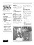
Transcription of Dinli ATV Ignition System Tests
1 Dinli ATV Ignition System Tests **To Override the safety brake switch and the tether cord unplug the two wires connected to them and plug them into each other. If there is a No Spark condition is still present perform the following test. STATOR Pulsar Pickup coil BLK-WH/RD 500 OHMS + 20% Charge Coil BLK-BLK/RD 800 OHMS + 20% Light coil BLK-Y/R .5 OHMS + 20% Light coil BLK-WH .6 OHMS + 20% ** Test all wires on flat plug to ground. ** Unplug BLK/R Wire and should have 95 Volts AC while cranking. Ignition SWITCH ON POSITION Green to Black wire has continuity. ON POSITION Red to Brown wire has continuity. LEFT SWITCH ASS. Red On Off Switch- On position Black to Blk/Wt has continuity. Starter Button-Blu/Wt to Grn/Brwn has continuity when button is depressed. CDI OUTPUT ** Disconnect Orange and Black wire connections. Test Orange wire output should have 65 volts AC Test Black wire output should have 35 volts AC ** Ground Black wire and retest Orange wire.
2 Orange Wire should have voltage now of 30-45 Volts AC The BLK/WT wire should be a ground via the tether switch. On models with the remote shut off the BLK/WT wire is a ground via the remote receiver box and tether switch REMOTE SHUT OFF System The remote Receiver unit has four wires connected to it. The unit controls the ground to the BLK/WT wire of the CDI unit. Red wire should have 12 volts constant. The ON/OFF switch provides 2 wires which are grounds. BOX Connector 1 o o2 Red Green 3 o o4 Black Green Harness Connector 2o o1 Blk/Wt Red 4o o3 Blk/Wt Blk/Wt To bypass System connect the three Black and White wires of the Harness.