Transcription of Direct Drive Servo Valves D633 and D634 Series - …
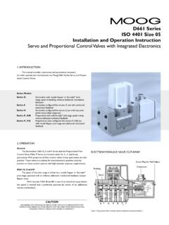
1 SERVOVALVES. Direct Drive SERVOVALVES. d633 /D634. Rev. 2, 04/2009. SERVOVALVES. FOR ELECTROHYDRAULIC POSITION, VELOCITY, PRESSURE OR FORCE CONTROL SYSTEMS. WITH HIGH DYNAMIC RESPONSE REQUIREMENTS. ISO 4401 SIZES 03 AND 05. What moves your world GENERAL. d633 -D634. SECTION PAGE MOOG Servo - AND PROPORTIONAL CONTROL Valves . General 2 For over 25 years Moog has manufactured proportional con- Benefits and Function 3 trol Valves with integrated electronics. During this time more than 150,000 Valves have been delivered. These Servo control General technical dates, Symbols 4 Valves have been proven to provide reliable control including injection and blow molding equipment, die casting machines, Electronics 5 presses, heavy industry equipment, paper and lumber proces- Technical Data 7 sing and other applications. Ordering Information 13 d633 AND D634 Series Servo CONTROL Valves . The d633 and D634 Series are Direct Drive Valves (DDV) with electric closed loop spool position control.
2 These Valves are throttle Valves for 3-, 4-, and 2x2-way applica- tions. They are suitable for electrohydraulic position, velocity, pressure or force control systems including those with high dynamic response requirements. The spool Drive device is a permanent magnet linear force motor which can actively stroke the spool from its spring centred posi- tion in both directions. This is an advantage compared with pro- portional solenoids with one force direction only. The closed loop spool position electronics and pulse width modulated (PWM) Drive electronics are integrated into the valve. The integrated electronics of the Valves is a new development featuring SMD technology with pulse width modulated (PWM). current output stage and requires a 24 VDC power supply. The valve Series described in this catalogue have successfully passed EMC tests required by EC Directive. Please refer to the respective references in the electronics section.
3 Valves available with explosion protection to EN 50018 and 55019, class II 2G EExde B+H2 T4, DMT 00 ATEX E 037, CE 0470. at d633 Series and II 2G EExde B+H2 T3, DMT 00 ATEX E 037, CE 0470 at D634 Series . Note: Installation dimensions and electric connection altered. Special data sheet on request. NOTICE This catalogue is for users with technical knowledge. To ensu- re that all necessary characteristics for function and safety of Before installation of the valve into the system the complete the system are given, the user has to check the suitability of the hydraulic system must be flushed. products described herein. In case of doubt please contact Please read the notes in section Electronics , page 6. Moog. Our quality management system is conform to DIN EN ISO 9901. 2 MOOG d633 /D634 Series BENEFITS AND FUNCTION. d633 -D634. OPERATIONAL BENEFITS OF Direct Drive Servo Valves (DDV).
4 Directly driven by a permanent magnet linear force motor Standardised spool position monitoring signal with low with high force level residual ripple No pilot oil flow required Electric null adjust Pressure independent dynamic performance With loss of supply voltage, or broken cable, or emergency Low hysteresis and low threshold stop the spool returns to its spring centred position without Low current consumption at and near hydraulic null passing a load move position. Direct Drive VALVE (DDV) OPERATION. The position control loop for the spool with position transdu- The demodulated spool position signal is compared with the cer and linear force motor is closed by the integrated electro- command signal and the resulting spool position error causes nics. An electric signal corresponding to the desired spool posi- current in the force motor coil until the spool has moved to its tion is applied to the integrated electronics and produces a pulse commanded position, and the spool position error is reduced width modulated (PWM) current to Drive the linear force motor.
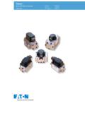
5 To zero. The resulting spool position is thus proportional to the An oscillator excites the spool position transducer (LVDT) pro- command signal. ducing an electric signal proportional to spool position. d633 Series single stage Null adjust cover plug Servo Control Valve Valve connector Spool Bushing Hydraulic symbol: Symbol shown with electric supply on and zero command signal. Integrated electronics Position transducer Linear force motor Centering spring PERMANENT MAGNET LINEAR FORCE MOTOR OPERATION. The linear force motor is a permanent magnet differential motor. The permanent magnets provide part of the required Cable hole Permanent magnets Centering springs magnetic force. For the linear force motor the current needed is considerably lower than would be required for a comparable proportional linear force motor has a neutral mid- position from which it generates force and stroke in both direc- tions.
6 Force and stroke are proportional to current. High spring stiffness and resulting centering force plus external forces ( flow forces, friction forces due to contamination). must be overcome during out-stroking. During backstroking to centre position the spring force adds to the motor force and provides additional spool driving force which makes the valve very less contamination sensitive. The linear force motor needs very low current in the spring centred position. Proportional solenoid systems require for the same function two solenoids with more cabling. Another solution uses a single solenoid, working against a spring. In case of current loss in the solenoid, the spring drives the spool to the end position by pas- Bearing Coil Armature Plug sing through a fully open position. This can lead to uncontrol- led load movements. MOOG d633 /D634 Series 3. GENERAL TECHNICAL DATES, SYMBOLS.
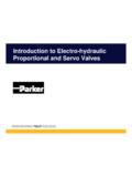
7 d633 -D634. PERFORMANCE SPECIFICATIONS FOR STANDARD MODELS 4-WAY FUNCTION. Operating pressure range Ports P, A and B up to 350 bar (5000 psi). Port T see data for individual Series Temperature range Ambient 20 C to +60 C (-4 F to +140 F). Fluid 20 C to +80 C (-4 F to +170 F). Seal material NBR, FPM, others on request Operating fluid mineral oil based hydraulic fluid (DIN 51524, part 1 to 3), 4-way version others on request spring centred Viscosity recommended 15 to 100 mm2/s Flow control (throttle valve) in port A and port B. allowed 5 to 400 mm2/s Port Y required if pressure pT > 50 bar (715 psi) in port T. System filtration for 3-way function close port A or port B of the manifold High pressure filter (without bypass, but with dirt alarm) moun- Spools with exact axis cut, 1,5 to 3 % or 10 % overlap ted in the main flow and if possible directly upstream of the available valve.
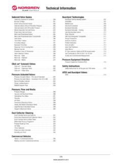
8 Class of cleanliness 2X2-WAY FUNCTION. The cleanliness of the hydraulic fluid particularly effects the performance (spool positioning, high resolution) and wear (metering edges, pressure gain, leakage) of the Servo valve. Recommended cleanliness class For normal operation ISO 4406 < 15 / 12. For longer life (wear) ISO 4406 < 14 / 11. Filter rating recommended For normal operation 10 75 (10 m absolute). For longer life (wear) 6 75 ( 6 m absolute). Installation options any position, fixed or movable Vibration 30 g, 3 axes 2x2-way version Degree of protection EN60529: class IP 65 with (Y-Port required). mating connector mounted Flow control (throttle valve) in port A. Shipping plate Delivered with an oil sealed Port Y required shipping plate Connect externally port P with port B, and port A with port T. Flow rate Q [l/min]. VALVE FLOW CALCULATIONS. The actual valve flow is dependent on the spool position and the pressure drop across the spool lands.
9 At 100% command signal ( +10 VDC = 100% valve opening). pmax = 350 bar (5000 psi). the valve flow at rated pressure drop pN = 35 bar per mete- ring land is the rated flow QN. For other than rated pressure drop the valve flow changes at constant command signal accor- ding to the square root function for sharp edged orifices. Q [l/min] = calculated flow QN [l/min] = rated flow p [bar] = actual valve pressure drop pN [bar] = rated valve pressure drop The real valve flow Q calculated in this way should result in an average flow velocity in ports P, A, B or T of less than 30 m/s. Valve pressure drop p [bar]. 4 MOOG d633 /D634 Series ELECTRONICS. d633 -D634. GENERAL REQUIREMENTS FOR VALVE ELECTRONICS. Supply 24 VDC, min. 19 VDC, max. 32 VDC EMC: Meets the requirements of Current consumption IAmax for d633 A emission: EN55011:1998+A1:1999 (limit class: B) and for D634 A immunity: EN61000-6-2:1999.
10 External fuse per valve for d633 A (slow) Minimum cross-section of all leads mm2 ( in2). for D634 A (slow) Consider voltage losses between cabinet and valve. All signal lines, also those of external transducers, shielded. Note: When making electric connections to the valve (shield, Shielding connected radially to (0 V), power supply side, protective earth) appropriate measures must be taken to and connected to the mating connector housing (EMC). ensure that locally different earth potentials do not result in excessive ground currents. See also Moog Application Note TN 353. MOOG d633 /D634 Series 5. ELECTRONICS. d633 -D634. VALVE ELECTRONICS WITH SUPPLY VOLTAGE 24 VOLT AND 6+PE POLE CONNECTOR. Command signal 0 to 10 mA Actual value 4 to 20 mA. floating, Valves with current command input The actual spool position value can be measured at pin F (see The spool stroke of the valve is proportional to ID = IE.)