Transcription of Direct Torque Controlled Drive Train for Electric Vehicle
1 Proceedings of the World Congress on Engineering 2012 Vol II. WCE 2012, July 4 - 6, 2012, London, Direct Torque Controlled Drive Train for Electric Vehicle A. Tashakori, Member IAENG and M. Ektesabi, Member IAENG. Abstract Electric Vehicle (EV) due to its running zero compared and BLDC has been recommended for high emission, sustainability and efficiency is of interest for future performance Electric Vehicle . Back-EMF monitoring, flux transportation. In-wheel technology has been one of the main linkage-based technique and free-wheeling diode conduction research concentration points in last decade. BLDC motor is on demand for in-wheel application because of its high efficiency, are some of sensorless control methods that can be used to Torque /speed characteristics, high power to size ratio, high commutate BLDC motor instead of using sensors [3]. operating life and noiseless operation. In this paper Direct Reducing complexity of motor construction, cost and Torque control (DTC) switching technique of BLDC motor for maintenance are obvious advantages of sensorless control EV propulsion system is proposed and simulated in MATLAB/ techniques but sensing back-EMF at low speeds, transient SIMULINK.
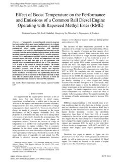
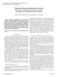
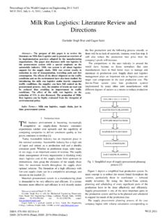
2 The Simulation results show effective control of time and discontinuous response due to high commutation Torque and remarkable reduction of Torque ripple amplitude as compared to conventional reported switching techniques. rates are its disadvantages. Improvements of in-wheel motor's Torque controllability result to have more efficient and safer Electric Vehicle . The simulation results of proposed switching system are satisfactory and show correct performance of system. Index terms BLDC motor; In-wheel motors; Direct Torque control (DTC); Electric Vehicle . I. INTRODUCTION. I DEA of using electricity instead of fossil fuels for propulsion system of vehicles is not new. Scientists and manufacturers have attempted to design or improve Electric vehicles from long time ago. Rodert Anderson built the first Electric carriage in 1839. In 1870 David Salomon developed Fig. 1 Four-wheel Drive Train system of an IFECV. an Electric car with a light Electric motor.
3 The batteries were heavy at that time; therefore performance was poor [1]. Priceless researches and works have been discussed for Nowadays hybrid vehicles are more popular due to better developing different control algorithms of BLDC motor [3- mileage and lack of enough infrastructures for charging 7]. Sensorless control technique with a new flux linkage battery of Electric vehicles. Applying in-wheel technology function has been reported for BLDC motors [3]. This will increase efficiency and safety of Electric vehicles. Using method improves problem of sensorless control techniques in-wheel technology, by wire technology and intelligent at low speeds. A speed-independent position function named control systems instead of conventional hydraulic or G( ) has been defined with respect to mechanical angle of pneumatic control systems result to an Intelligent Fully rotor. This technique is able to detect position of rotor at Electronically Controlled Vehicle (IFECV) [2].
4 Schematic around of nominal speed. It is suitable for in-wheel diagram of four wheel Drive Train of an IFECV is shown in application because we need to control the motor from stall Fig. 1. position. Four-switch converter with the current Controlled Improving performance of in-wheel motor and its PWM control technique has been proposed for BLDC [4]. controller can increase efficiency, controllability and safety Difficulties in generating 120 conducting current profiles in of Electric vehicles. Various electrical motors have been three phase winding of BLDC with four-switched converter used by manufacturers in last decades. Brushed DC, and current distortion in two phase cause by back-EMF of induction, switched reluctance and BLDC motors have been silent phase are main problems of proposed technique. A. new power supply, DSP- Controlled PWM chopper and C- Manuscript received Feb 16, 2012; revised March 16 2012. Paper title is dump converter has been presented [5].
5 A dual speed and Direct Torque Controlled Drive Train for Electric Vehicle . Alireza Tashakori Abkenar is PhD candidate in Faculty of Engineering current closed-loop control is used to keep ratio of voltage and Industrial Science, Swinburne University of Technology, Melbourne, to frequency constant to have constant Torque operation of Australia(phone: +61392144610; e-mail: atashakoriabkenar@ ). motor. Forced commutation RC circuits and snubber circuits Mehran Motamed Ektesabi is with Faculty of Engineering and Industrial Science, Swinburne University of Technology, Melbourne, Australia to control commutation and dv/ dt rating on switches have (phone: +61392148532; e-mail: mektesabi@ ). been discussed. Simulation results show number of current ISBN: 978-988-19252-1-3 WCE 2012. ISSN: 2078-0958 (Print); ISSN: 2078-0966 (Online). Proceedings of the World Congress on Engineering 2012 Vol II. WCE 2012, July 4 - 6, 2012, London, spikes which cause increase on Torque ripple of BLDC.
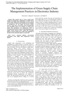
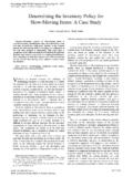
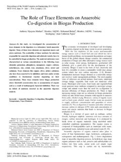
6 Motor which is not suitable for in-wheel application. An adaptive fuzzy control scheme via parallel distributed compensation has been applied to control velocity of small BLDC motors [6]. Simulation results show stable velocity control of BLDC motor in case of any parameter perturbation. Although stability and smoothness of Torque is essential in high performance EV's, but it would be constructive for other applications like scooters and Electric bikes. A digital controller of BLDC motor with two mode of operation, namely conduction angle control and current mode control has been introduced [7]. Torque is directly proportional to current in BLDC, thus current control results to Torque control of motor. Speed ripple of BLDC is reduced via proposed digital controller up to maximum of percent. This method could be more suitable for EV. application if Torque ripple reduction also has been considered. Fig. 2 Overall block diagram of DTC for BLDC motor DTC technique is a sensorless control technique.
7 It does Accurate estimation of flux linkage magnitude and Torque not use any sensor for detecting rotor position. Torque is required for DTC of in-wheel motors. In some techniques, control is one of important factors in Drive Train of Electric Current sensors have been used to determine flux linkage Vehicle . Reduction of Torque ripples cause to deliver and estimate voltage from DC bus of inverter [12], [14] and smoother power to the wheel. Delivering as minimum as [15]. This method is too sensitive to voltage errors caused possible ripple free Torque with desired value to the wheels by dead-time effects of inverter switches, voltage drop of in various conditions, essentially increase safety and power electronic devices and fluctuation of DC link voltage efficiency of Electric Vehicle . Therefore DTC switching [16]. Therefore in this paper both current and voltage technique is recommended for high performance Electric sensors are used for estimation of flux linkage magnitude vehicles.
8 And Torque [13]. In this paper Direct Torque control (DTC) switching Precise estimation are mainly depends on accurate technique of BLDC motor for EV propulsion system is sensing of currents and voltages. Variations of stator proposed. Principle of DTC switching technique of three resistance due to changes of temperature cause error in phase BLDC motor for Electric Vehicle applications is stator flux estimation. Pure analogue integrator also explained in section two. Simulation results of proposed produces DC offset in signal. Different techniques have Direct Torque control switching technique of BLDC motor been discussed to solve analogue integrator DC drift error are shown and discussed in section [17]. As it is considered that BLDC motor is working in constant Torque region and there is no need of flux II. Direct Torque CONTROL OF BLDC USING THREE magnitude change during operation; second algorithm PHASE CONDUCTION MODE proposed in [17] with limiting level of 2 K L /(3 3 ) is Direct Torque control (DTC) was proposed for the first used where K L is flux linkage of motor.
9 Time by Takahashi and Noguchi in 1986 [8] and Depenbrock in 1988 [9] for induction motors. Recently, many researches Clarke transformation is used to convert balanced three worked on DTC of BLDC motor for specific applications phase system (voltages and currents) to -axis references. which needs precise Torque control. Various methods of Therefore stator flux linkage magnitude, stator flux angle implementing DTC of BLDC have been reported [10-15]. and electrical Torque of BLDC motor can be estimated by, DTC technique of BLDC has been applied to Drive Train of hybrid Electric Vehicle [15]. Overall block diagram of DTC S = (VS RiS ).dt (1). of BLDC motor is shown in Fig. 2. Torque error, stator flux error and stator flux angle are S = (VS RiS ).dt (2). regularly used to select proper voltage space vector for switching in DTC technique. In this paper flux linkage error r = S LiS (3). is eliminated Because of variations of stator flux magnitude regarding changes in resistance, current and voltage and r = S LiS (4).
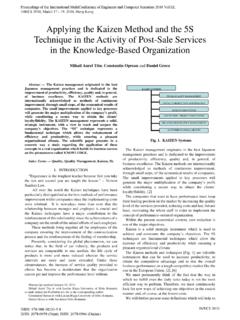
10 Specifically sharp dips at every commutation [10]. BLDC. operates in both constant Torque region and constant power S = S2 + S2 (5). region. Back-EMF of motor is below DC voltage source of inverter in constant Torque region (below base speed) and is . increased more than DC voltage value above nominal speed. S = tan 1( S ) (6). Therefore stator inductance avoids abrupt increase of phase S . current and deteriorates output Torque of motor. Therefore in this paper operation of BLDC motor is considered at d r . e = (7). constant Torque region. dt ISBN: 978-988-19252-1-3 WCE 2012. ISSN: 2078-0958 (Print); ISSN: 2078-0966 (Online). Proceedings of the World Congress on Engineering 2012 Vol II. WCE 2012, July 4 - 6, 2012, London, d r TABLE I. e = (8). THREE PHASE CONDUCTION SWITCHING FOR DTC OF BLDC. dt Torque FLUX ANGLE SECTORS. 3 P e e ERROR. Te = iS + iS (9) 1 2 3 4 5 6. 2 2 . 1 101 100 110 010 011 001 . 0 110 010 011 001 101 100 . Where, : Stator resistance III.