Transcription of Direction Finding Antennas
1 Chapter 14. Direction Finding Antennas he use of radio for Direction - Finding purposes (RDF) is almost as old as its application for com- T munications. Radio amateurs have learned RDF techniques and found much satisfaction by par- ticipating in hidden transmitter hunts. Other hams have discovered RDF through an interest in boating or aviation where radio Direction Finding is used for navigation and emergency location systems. In many countries of the world, the hunting of hidden amateur transmitters takes on the atmo- sphere of a sport, as participants wearing jogging togs or track suits dash toward the area where they believe the transmitter is located.
2 The sport is variously known as fox hunting, bunny hunting, ARDF. (Amateur Radio Direction Finding ) or simply transmitter hunting. In North America, most hunting of hidden transmitters is conducted from automobiles, although hunts on foot are gaining popularity. There are less pleasant RDF applications as well, such as tracking down noise sources or illegal operators from unidentified stations. Jammers of repeaters, traffic nets and other amateur operations can be located with RDF equipment. Or sometimes a stolen amateur rig will be placed into operation by a person who is not familiar with Amateur Radio, and by being lured into making repeated transmis- sions, the operator unsuspectingly permits himself to be located with RDF equipment.
3 The ability of certain RDF Antennas to reject signals from selected directions has also been used to advantage in reducing noise and interference. Although not directly related to Amateur Radio, radio navigation is one application of RDF. The locating of downed aircraft is another, and one in which amateurs often lend their skills. Indeed, there are many useful applications for RDF. Although sophisticated and complex equipment pushing the state of the art has been developed for use by governments and commercial enterprises, relatively simple equipment can be built at home to offer the radio amateur an opportunity to RDF.
4 This chapter deals with Antennas which are suited for that purpose. RDF by Triangulation It is impossible, using amateur techniques, to pinpoint the whereabouts of a transmitter from a single receiving location. With a directional antenna you can determine the Direction of a signal source, but not how far away it is. To find the distance, you can then travel in the determined Direction until you discover the transmitter location. However, that technique does not normally work very well. A preferred technique is to take at least one additional Direction measurement from a second re- ceiving location.
5 Then use a map of the area and plot the bearing or Direction measurements as straight lines from points on the map representing the two locations. The approximate location of the transmit- ter will be indicated by the point where the two bearing lines cross. Even better results can be obtained by taking Direction measurements from three locations and using the mapping technique just described. Because absolutely precise bearing measurements are difficult to obtain in practice, the three lines will almost always cross to form a triangle on the map, rather than at a single point.
6 The transmitter will usually be located inside the area represented by the triangle. Additional information on the technique of triangulation may be found in recent editions of The ARRL Handbook. Direction Finding Antennas 14-1. Direction Finding SYSTEMS. Required for any RDF system are a directive antenna and a device for detecting the radio signal. In amateur applications the signal detector is usually a receiver; for convenience it will have a meter to indicate signal strength. Unmodified, commercially available portable or mobile receivers are generally quite satisfactory for signal detectors.
7 At very close ranges a simple diode detector and dc microammeter may suffice for the detector. On the other hand, Antennas used for RDF techniques are not generally the types used for normal two-way communication. Directivity is a prime requirement, and here the word directivity takes on a somewhat different meaning than is commonly applied to Antennas . Normally we associate directivity with gain, and we think of the ideal antenna pattern as one having a long, thin main lobe. Such a pattern may be of value for coarse measurements in RDF work, but precise bearing measure- ments are not possible.
8 There is always a spread of a few (or perhaps many) degrees on the nose of the lobe, where a shift of antenna bearing produces no detectable change in signal strength. In RDF. measurements, it is desirable to correlate an exact bearing or compass Direction with the position of the antenna . In order to do this as accurately as possible, an antenna exhibiting a null in its pattern is used. A null can be very sharp in directivity, to within a half degree or less. Loop Antennas A simple antenna for RDF work is a small loop tuned to resonance with a capacitor.
9 Several factors must be considered in the design of an RDF loop. The loop must be small compared with the wave- length. In a single-turn loop, the conductor should be less than wavelength long. For 28 MHz, this represents a length of less than 34 inches (diameter of approximately 10 inches). Maximum response from the loop antenna is in the plane of the loop, with nulls exhibited at right angles to that plane. To obtain the most accurate bearings, the loop must be balanced electrostatically with respect to ground. Otherwise, the loop will exhibit two modes of operation.
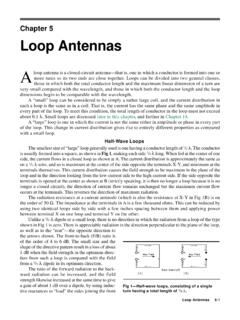
10 One is the mode of a true loop, while the other is that of an essentially nondirectional vertical antenna of small dimensions. This second mode is called the antenna effect. The voltages introduced by the two modes are seldom in phase and may add or subtract, depending upon the Direction from which the wave is coming. The theoretical true loop pattern is illustrated in Fig 1A. When properly balanced, the loop exhibits two nulls that are 180 apart. Thus, a single nullreading with a small loop antenna will not indicate the exact Direction toward the transmitter only the line along which the transmitter lies.