Transcription of Directional cetop valves DCV 03 - hidrapa.com.br
1 Catalogue Directional cetop valves Fluid Power DCV 03. u i d r P l u e r i d F. l F ow lu r e i d F o w l u r . e . P F e id P F w i d d w r o u . u wer d Po Flu owe id P r Fl P.. i . P o lui er P Flu we id . d F ow lui r d o l u e . e r . P F e d P F w w lui d r . o w u i e r Po . e P F l w id r F Pow uid r P o . l u e . e . i d F l w u i d F o w l u o l r P F.. Fl wer id P r F owe uid er P.. P o Flu we P F l ow id d r P o u i d r P . l u e . e i d F l w u i d F o w w o F l u r . P o F l e r P.. w e id r o w . u i d e r e r Po lu we . P F l o w w id r F Po uid er . P P . u l d F owe luid r F Pow Flui Fluid w l . P F w e id r r . P o . d er Po lu we . e id o w id r F . P o Po Flu er w P Flu we id id r o w . r . P o l F F u l u w de P F l Directional valves DCV 03. 2 Danfoss Fluid Power 03/99. Directional valves DCV 03.
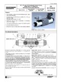
2 4/3-, 4/2- and 3/2-way Directional valves Cylindrical operating solenoids with separate operating coils connector can be turned in either direction by 90 . Four-land spool reduced functional dependence on fluid viscosity Push button manual override Installation dimensions to ISO 4401-03-02-0-94 and DIN 24340-A6. Functional Description The plug connectors (6, 7) can be turned by 90 . By loosening the fixing nut (8), the solenoids can be turned The Directional control valves DCV 03 consist of housing arbitrarily in the range of 360 , or replaced. This enables (1), a control spool (5) with two centering springs (4) and the operating coils to be replaced without opening the cylindrical operating solenoids (2, 3). pressure-tight spaces. The three-position Directional valves are fitted with two In the case of solenoid malfunction or power failure, the solenoids and two springs.
3 Two-position Directional spool of the valve can be repositioned by manual valves have either one solenoid and one return spring or override (9), provided the pressure in T-port does not two solenoids and a detent assembly. exceed 25 bar. The operating solenoids are solenoids. For The basic surface treatment of the valve housing (1) is supply the solenoids are provided with a rectifier, which is phosphate coated and the operating solenoids (2, 3) are integrated directly into the connectors. zinc coated. 9 8 2 6 7 3 8 9. 4 1 5 4. Danfoss Fluid Power 03/99 3. Directional valves DCV 03. Ordering Code DCV 03 /. Solenoid operated Directional valves Sensing of the end position no designation without sensing S1 sensing of the end position Nominal size Sealing no designation NBR. V FPM (VITON). Number of operating positions two positions 2.
4 Three positions 3. Orifice in P port no designation without orifice D1 mm D2 mm Functional symbols D3 mm see the table Functional symbols D4 mm D5 mm Rated supply voltage of solenoids (at the coil terminals) Damping 12 V / A 01200 no designation without damping 14 V / A 01400 T1 Orifice in solenoid 21 V / A 02100. 24 V / A 02400. 42 V / A 04200. 48 V / A 04800. 60 V / A 06000 Manual override 102 V / A 10200 no designation standard 205 V / A 20500 N1 covered with closing nut 24 V / A / 50 (60) Hz 02450 N2 covered with rubber protective 115 V / A / 50 (60) Hz 11550 N3 with detent assembly 230 V / A / 50 (60) Hz 23050. The coils correspond with E5 type Connector plug to DIN 43 650. no designation without connector plug K1 connector plug without rectifier Type of the solenoid coil K2 connector plug without rectifier with DIN connector E1 and with LED.
5 With DIN connector and K3 connector plug with rectifier quenching diode E2 K4 connector plug with rectifier and LED. with AMP connector E3. with AMP connector and quenching diode E4. with integrated rectifier and DIN connector E5. Recommended solenoid coils used with connector plugs with rectifiers type designation K3, K4. Rated supply source voltage Type designation of the solenoid voltage (permissible rated voltage variation 10%. 24 V / A / 50 (60) Hz 02100. 115 V / A / 50 (60) Hz 10200. 230 V / A / 50 (60) Hz 20500. 4 Danfoss Fluid Power 03/99. Directional valves DCV 03. Technical Data Nominal size (mm) 6. Maximum flow US GPM ( l/min) See p-Q characteristics Max. operating pressure at ports P, A, B psi (bar) 4641 (320). Max. operating pressure at port T psi (bar) 2320 (160). Pressure losses psi (bar) see p-Q characteristics Hydraulic oils of power classes HM, HV to cetop .)
6 Hydraulic fluid RP91 H in viscosity classes ISO VG 32, 46 and 68. Fluid temperature range F ( C) 13 +158 ( 25 +70). Ambient temperature range F ( C) 13 +122 ( 25 +50). Viscosity range SUS (mm 2 /s) 98 1840 (20 400). Maximum degree of fluid contamination Class 18/15 to ISO 4406. Therefore we recommend a filter with a retention rata 10 75. Permissible rated voltage variation % : 10 +6 : 10. Max. switching frequency 1/h Switching time, on: at = 98 SUS (20 mm 2 /s) ms : 30 50 : 30 40. Switching time, off: at = 98 SUS (20 mm 2 /s) ms : 10 50 : 30 70. Duty cycle % 100. Service life cycles 10 7. Enclosure type to DIN 40050 IP 65. Weight valve with 1 solenoid LB (kg) ( ). valve with 2 solenoids ( ). Mounting position optional Danfoss Fluid Power 03/99 5. Directional valves DCV 03. Functional Symbols Designation Symbol Interposition Designation Symbol Interposition 6 Danfoss Fluid Power 03/99.
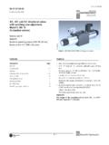
7 Directional valves DCV 03. Characteristics p-Q Characteristics measurement at = 166 SUS (35 mm2/s) and t = 104 F (40 C). Operating limits for maximum hydraulic power transferred by the Directional valve. Z11 1. C11 7. H11 4. P11 1. Y11 3. L21 6. B11 9. Y41 7. Operating pressure in psi (bar). Z21 1. C41 6. F11 6. R11 4. R21 5. A51 6. P51 1. Y51 3. C51 7. Z51 1. Z71 8. Z81 8. Z91 8. R31 6. H51 8. F51 8. X11 4. K11 8. N11 8. Flow Q in GPM (l/min). J15 1. J75 10. p-Q Characteristics measurement at = 166 SUS (35 mm2/s) and t = 104 F (40 C). P-A P-B A-T B-T P-T. Z11 2 2 3 3. C11 5 5 5 6 3. H11 2 2 2 2 3. P11 1 1 3 3. Y11 2 2 2 2. Pressure loss p in psi (bar). L21 2 2 3 3. B11 2 2 3 3. Y41 3 3 3 3. Z21 2 3. C41 4 4 5. F11 1 2 3 3. R11 2 2 3 3. R21 2 2 3 3. A51 2 2. P51 1 3. Y51 2 2. C51 2 3 4. Z51 2 3. Z71 3 3. Z81 3 3.
8 Z91 3 3 3. R31 2 3. H51 2 3. F51 2 3. X11 2 2 3 3. K11 2 3. Flow Q in GPM (l/min) N11. J15 2 2 3 3. J75 2 2. Danfoss Fluid Power 03/99 7. Directional valves DCV 03. Valve dimensions Dimensions in millimeters Valve with two solenoids .. 6.. 8. 7. 4.. 3 1 5 2 3.. Valve with one solenoid Functional symbols R11, R21, A51, P51, Y51, Z51, C51, Z71, Z81, Z91, 1 Solenoid a R31, H51, F51 2 Solenoid b 3 Manual override 4 Name plate 5 Square ring supplied in delivery packet 6 4 mounting holes 7 Connector plug to DIN 43650. 8 Distance required to remove plug . Valve with one solenoid Functional symbols X11, Z11, C11, H11, K11, N11, F11. (Rmax. ). Required surface finish of interface 8 Danfoss Fluid Power 03/99. Directional valves DCV 03. Type of the solenoid coil Designation Dimensional sketch Description Solenoid coil with terminal for the connector plug to DIN 43 650.
9 E1. 34. Solenoid coil with integrated quenching diode and terminal for the connector plug to DIN 43 650. E2. Solenoid coil with terminal for AMP connector plug. E3. (30). Solenoid coil with integrated quenching diode and terminal for AMP connector plug. E4. Solenoid coil with integrated rectifier and terminal for the connector plug to DIN 43 650. 39. E5. Connector plug to DIN 43650. Designation Type Model Max. input voltage 250 V Plug B (black) without rectifier 230 V K1. 250 V Plug A (grey) without rectifier 230 V Plug B (black) without rectifier and with 12 30 V LED 230 V K2. Plug A (grey) without rectifier and with 12 30 V LED 230 V Plug B (black) with rectifier 250 V K3. Plug A (grey) with rectifier 250 V Plug B (black) with rectifier and with LED 250 V K4. Plug A (grey) with rectifier and with LED 250 V Danfoss Fluid Power 03/99 9.
10 Directional valves DCV 03. Manual override Standard Closing Nut Without designation Designation N1. Dimensional sketch Dimensional sketch . Description Description Standard model of the manual override. Manual override with closing nut. Standard fixing nut of the solenoid. Can be used after removing the nut. Rubber cap Detent Assembly Designation N2 Designation N3. Dimensional sketch Dimensional sketch Description Description Manual override protected Manual override enabling by rubber cap. spool arrestment in the chargd position. Cushioned spool shifting Designation Dimensional sketch Description This Directional valve provides cushioned 2 control spool shifting by means of orifice situated in the solenoid armature. To ensure the proper function of the valve, 1 perfect air bleeding of the solenoid is required T1 (by means of bleeding plugs (1).)