Transcription of Directional seated valves Type WN and WH - …
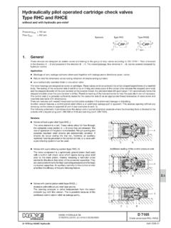
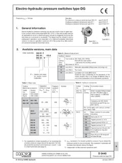
1 Directional seated valves Type WN and WHlzero leakage(Type WN also as Directional spool valve)D 7470 A/1 Directional seated valves WN and WHAugust 2008-00 HAWE HYDRAULIK SESTREITFELDSTR. 25 81673 M 1985 by HAWE HydraulikIndividual valves for manifold mountingSection 2 valves with individual connection sub-platesSection 3 Directional valve banksD 7470 B/1 Pressure pmax=350 .. 450 barFlow Qmax=5 .. 60 informationIndividual valve formanifold mounting (see section 2)Valve with indiv. connectionsub-plate for pipe connection (see section 3)Example as size 3 Size 1 Size 2 Size 3 Size 4'The Directional seated valves type WN and WH are of compact design and feature 2/2-, 3/2-way functions.
2 2/2-, 3/2-way functions are possible by combining two individual valves on one joint sub-plate (see sect 3).'All functionally important components, from the solenoid armature to the valve elements, are lubricated by the hydraulic fluid,therefore no maintenance is required.'Type WN is only available as size 1. The armature cavity is pressure resistant up to 300 bar and directly connected to port R. Thismeans that between the solenoid armature and the valve elements only a simple pin (with no seal) is required.
3 This results in avery long service life (no seal wear).The solenoid force is largely dependent on the respective pressures to be switched. This often enables operation with reducedsupply voltage (see sect. ) thereby reducing the solenoid temperature and increasing its service life.'Additionally to the Directional seated valve versions of type WN, there is also a 4/2-way Directional spool valve available(pmax= 300 bar). 'Type WH features an actuation pin between solenoid armature and valve elements which is sealed and shaped in such a way,that the solenoid force is supported by an additional hydraulic force.
4 This enables pressure up to 450 bar (WH 1) or 350 bar (WH 2, 3 and 4) to be lubrication purposes and to equalize the volume, the armature cavity is either connected internally to the return port, or incase of 2/2-way valves connected externally to the return pipe (depending on application). Type WH 1 features larger valve elements and more stroke resulting in a reduced flow resistance than with WN 7470 A/1 page valve for manifold mountingFor valves with individual sub-plate suited for pipe connection, see section coding, main dataFor complete type overview see section , page 19 Coding example:WH 1 M - G 24 Table 1: Basic type and sizeTable 2: Actuation solenoid 5)Table 3.
5 Flow pattern symbols (also see section 3 for combinations of individual valves )TypePressure pmax(bar)Flow (lpm)1) See sect. ) The additional check valve on the P-side in types Q, E, N, R, and WX prevents an equalization of pressure when the passage is open, or a changein direction of flow when due to other switching operations the pressure atP becomes lower than at A (B, R).See also section 3, table 4 a footnote 3).The check valve insert can be retrofitted and is therefore separately available.
6 Order coding EK ) See also installation instruction in sect. ) Not available for WH 4 5) For further special voltage see section Special voltages SuitedforWN 12/2-wayWN 13/2-wayWH1 toWH 42/2-wayWH1 toWH 43/2-wayDirectional seated valvesDirectional seated valvesDQ2)3)FE2)WHN2)3)MR2)WXHN2)MR2)DQ2 )FE2)Only for WN 1, WH 1 and WH 2:3/2-way valvesH1with additionalN1return pressureM1stopR1 When several valves are operating in parallel,the return pressure stop prevents pressuresurges out of the common return pipe from entering unoperated, unloaded or easily movingconsumers, where there is a connection A preventing uncontrolled movements.
7 Suchpressure surges can arise as a result of switch-ing operations. Occasionally the return pressurestop may be required for WN 1 or WN 2 valves ,as the resetting spring has a lower force than inWH1. These check valves are not suitable forstopping pressurized oil, which may be apparent at R, depending on the combination ofvalves. A circuit with an external check valvewould have to be installed in this case. Directionalseated 350 1)450350350350 Directionalseated valve58153060 Directionalspool valve300 Directionalspool valve6WN 1WH 1WH 2WH 3WH 4 StandardWithoutWith 'sG 12 4)X 12 4)L 12 4)12 V DCG 24X 24L 2424 V DCG 98 4)X 98 4)---98 V DCG 205 X 205---205 V DCWG 110 4)------110 V ACWG 230------230 V ACThe following parts are required for retrofitting:WN(H) 1 Valve shim 7470 021WH 2 Ball 3/16 DIN 5401 andhousing 7545 019 Only for WN 1, WH 1.
8 2/2- and 3/2-way directionalseated valves feature an additional orifice in port P, flow pattern symbols D, F, H and M(see also sect. ).50 /60Hz2/2-way Directional seat-ed valves featuring apressure limiting valve inthe intermediate plate,flow pattern symbols Dand F (see also sect. ).D 7470 A/1 page characteristic and hydraulicNomenclature, designSeated ball valve or spool valve in 2/2-, 3/2- or 4/2-way versions, depending on typePipe connectionBasic valve(sect.)
9 : Via manifoldSub-plates(sect. 3):Via tapped portsPortsP = Inlet (pump side); A, B = Consumers; R = ReturnL = Relief port, connect pressureless to the tank (return) alwaysFor pressure rating, see belowInstalled positionAnyFlow resistanceSeated valves :Only in arrow direction in accordance with symbolSpool valves :Preferably in arrow direction (see symbol W/WX in sect. ). Contrary to the arrow direction is permissible; Note pressure rating of R (see below )Overlapping3/2-wayNegative. Transition from one to the other flow direction is only completed whenseated valvesend position is achieved all passages are interconnected during the switching operation.
10 The switching operation is unhampered by this, due to their quick valves :NoneFlow (lpm)Operation pressurePorts P, A and BPerm. pressure in port RWN 1:pR 350 bar, but observe that pR pA pP!Note: Use code letter F and E as straight-way valve up to 320 bar only!WH 1 (2, 3 a. 4): Flow pattern symbols H, N, M and R pR 20 bar Flow pattern symbols D, Q, F and E pR 350 bar, pL 20 bar Sub-plates acc. to sect. 3: Version ..S(SR) or ..V(VR) pR 20 bar Pressure fluidHydraulic oil conforming DIN 51524 part 1 to 3: ISO VG 10 to 68 conforming DIN limits: min.