Transcription of Disconnect switches - ABB Ltd
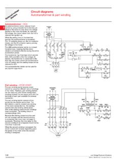
1 Disconnect switches Di s Non-fusible Disconnect switchess co No witc nne 16A 3150A, 600V n- he ct fus s ibl e ABB SwitchLine includes 16 different amperage sizes from 16A to 3150A. The basic construction provides flexibility, safety, and high performance in an extremely compact size. ABB SwitchLine is a perfect choice for all switching applications from industrial motor control to construction safety switches . International acceptance 18. UL listed, CSA approved, IEC rated, CE marked, and most other international standards. Non-fusible UL98 (CSA ) UL File # E101914, CSA File #LR58077. For OT30, OT60, OT100, OT125, OT200, OT400, OT600, OETL-NF800 OETL-NF2000 switches , OH_ pistol grip handles Suitable for use as motor disconnects or industrial control panel disconnects on service entrance equipment, panelboards, switchboards, industrial control equipment, motor control centers, etc.
2 And are horsepower rated and ampere rated. UL508 (CSA No. 14) UL File # E63822, CSA File #LR58247. For OT16 OT80 switches , OH_ selector handles Suitable for use in equipment or machinery as motor controllers & motor disconnects and are horsepower and ampere rated. IEC. Tested in accordance to IEC 947-1 and 3, IEC 664, IEC 269, and IEC 204. CE. Compliance with the European Machine Directive IEC 204 (EN 60204). Low Voltage Products & Systems ABB Inc. 888-385-1221 1 SXU000023C0202. ct n ne s General information o he e sc l Selection guide Di witc usib s -f No n OT16F3 OT160E3. OT16F3 OT25F3 OT40F3 OT63F3 OT80F3 OT30F3 OT60F3 OT100F3 OT160E3. Catalog number 3 pole OT16F3 OT25F3 OT40F3 OT63F3 OT80F3 OT30F3 OT60F3 OT100F3 OT160E3.
3 General purpose A 16 25 40 60 80 30 60 100 125. amp rating Approvals 1. 2 pole N/A N/A N/A N/A N/A N/A N/A N/A UL98. 3 pole UL508 UL508 UL508 UL508 UL508 UL98 UL98 UL98 UL98. 4 pole UL508 UL508 UL508 UL508 UL508 UL98 UL98 UL98 UL98. Technical ratings UL,CSA 2 Max operating voltage V 600 600 600 600 600 600 600 600 600. Max horsepower rating Three phase 240V HP 5 10 15 20 10 20 30 40. 480V HP 10 15 20 30 40 20 40 50 75. 600V HP 10 20 25 30 40 30 40 50 100. Single phase 120V HP 1 2 2 2 2 3 5 240V HP 2 3 5 5 5 5 15 20. Technical ratings IEC2 Rated insulation and operational voltage. AC20 and DC20 V 750 750 750 750 750 750 750 750 750. Rated thermal current, Ith AC 20/DC 20 open A 25 32 40 63 80 40 63 115 200.
4 AC 20/DC 20 enclosed A 25 32 40 63 80 40 63 115 160. AC 21A 500V A 16 25 32 63 80 40 63 100 160. 690V A 16 25 32 63 80 40 63 100 160. Rated operational power AC23. 400/415V kW 9 11 22 37 15 37 75. 690V kW 9 11 15 15 15 37 75. Physical characteristics Weight 3 3 pole lb Dimension 3 pole H in W in D in 18 Accessories Terminal lug kit Integral Integral Integral Integral Integral Integral Integral Integral Integral Terminal shroud . Auxiliary contact . Shaft/handle diameter 6mm 6mm 6mm 6mm 6mm 6mm 6mm 6mm 6mm .24" x .24" .24" x .24" .24" x .24" .24" x .24" .24" x .24" .24" x .24" .24" x .24" .24" x .24" .24" x .24". Handle UL/NEMA type Type 1, 3R, 12 . Type 1, 3R, 4, 4X, 12 . Handle type Selector.
5 Pistol . Recommended pistol handle length 45 - 65mm 45 - 65mm 45 - 65mm 45 - 65mm 45 - 65mm 45 - 65mm 45 - 65mm 45 - 65mm 65 - 80mm Maximum recommended shaft length 290mm 290mm 290mm 290mm 290mm 290mm 290mm 290mm 290mm Conversion kits 6 pole . Transfer . Bypass . Mechanical interlock . Electrical interlock . = Available = Not available 1 UL listed switches are also CSA approved. 2 For complete technical information please see page 3 Switch only. Low Voltage Products & Systems 1 SXU000023C0202 ABB Inc. 888-385-1221 Di s General information s co No witc nne Selection guide n- he ct fus s OT200 OT600 & OETL-NF800A OETL-NF3150 ibl e OT200U03 OT400U03 OT600U03 OETL-NF800 ASW OETLNF1200SW OETL-NF1600SW OETL-NF2000SW OETL-NF3150SW.
6 Catalog number 3 pole OT200U03 OT400U03 OT600U03 OETL-NF800A OETL-NF1200 OETL-NF1600 OETL-NF2000 OETL-NF3150. General purpose A 200 400 600 800 1200 1600 2000 3150. amp rating Approvals 1. 2 pole N/A N/A UL98 & IEC UL98 & IEC UL98 & IEC UL98 & IEC UL98 & IEC IEC. 3 pole UL98 & IEC UL98 & IEC UL98 & IEC UL98 & IEC UL98 & IEC UL98 & IEC UL98 & IEC IEC. 4 pole UL98 & IEC UL98 & IEC UL98 & IEC IEC IEC IEC IEC IEC. Technical ratings UL,CSA 2 Max operating voltage V 600 600 600 600 600 600 600 600. Max horsepower rating Three phase 240V HP 75 125 200 250 . 480V HP 150 250 450 500 . 600V HP 200 350 500 600 . Single phase 120V HP . 240V HP . Technical ratings IEC 2 Rated insulation and operational voltage.
7 AC20 and DC20 V 1000 1000 1000 1000 1000 1000 1000 1000. Rated thermal current, Ith AC 20/DC 20 open A 250 400 800 1250 1600 2500 2500 3150. AC 20/DC 20 enclosed A 250 400 800 1250 1600 2300 2300 2600. AC 21A 500V A 250 400 800 1250 1600 25004 25004 31504. 690V A 250 400 800 1250 1600 25004 25004 31504. Rated operational power AC23. 400/415V kW 132 220 400 400 400 400 400 400. 690V kW 240 355 800 . Physical characteristics Weight 3 3 pole lb Dimension 3 pole H in 10 W in D in Accessories 18. Terminal lug kit OZXA-200 OZXA-400 OZXA-800 OZXA-30 OZXA-28 OZXA-28 OZXA-28/2 OZXA-28/2. Terminal shroud . Auxiliary contact . Shaft/handle diameter 6mm 12mm 12mm 12mm 12mm 12mm 12mm 12mm .24" x .24" .47" x.
8 47" .47" x .47" .47" x .47" .47" x .47" .47" x .47" .47" x .47" .47" x .47". Handle UL/NEMA type Type 1, 3R, 12 . Type 1, 3R, 4, 4X, 12 . Handle type Selector . Pistol . Recommended pistol handle length 65 - 80mm 125 - 175mm 125 - 175mm 125 - 175mm 125 - 175mm 125 - 175mm 125 - 175mm 125 - 175mm Maximum recommended shaft length 290mm 595mm 595mm 595mm 595mm 595mm 595mm 595mm Conversion kits 6 pole . Transfer . Bypass . Mechanical interlock . Electrical interlock . S = Standard feature = Available = Not available 1 UL listed switches are also CSA approved. 2 For complete technical information please see page 3 Switch only 4 IEC 947-3 Utilization Category B, Infrequent operation Low Voltage Products & Systems ABB Inc.
9 888-385-1221 1 SXU000023C0202. ct n ne s Selection information o he e sc l Di witc usib s -f n No Standard part number designation 1. Non-Fusible OT switches (16 to 125A). OT 16 F 3 C. Amperage 16 = 16 amps* 63 = 60 amps* 60 = 60 amps 25 = 25 amps* 80 = 80 amps* 100 = 100 amps 40 = 40 amps* 30 = 30 amps 160 = 125 amps Number of Poles 3 = 3 poles 4 = 4 poles 6 = 6 poles Special Configuration C = Double throw switch * UL508 listed switches . OT30_, OT60_, OT100_, and OT160_ are cUL98 listed Non-Fusible OT switches (200A and above). OT 200 U 03 C. Amperage 200 = 200 amps 400 = 400 amps 600 = 600 amps Number of Poles & Placement of Mechanism 02 = 2 poles to right of mechanism 04 = 4 poles to right of mechanism 03 = 3 poles to right of mechanism 40 = 4 poles to left of mechanism 30 = 3 poles to left of mechanism 22 = 2 poles to left, 2 poles to right of mechanism 12 = 1 pole to left, 2 poles to right of mechanism 13 = 1 pole to left, 3 poles to right of mechanism Special Configuration C = Double throw switch All OT200_, 400_, and 600_ switches are cUL98 listed.
10 Selector Handles OHB S 1 P H. Handle Color B = black Y = Red/Yellow Physical Size Connection to Switch A = external shaft P = snap on R = screw Protection Class H=1 J= 1, 3R, 12. 18 Pistol Handles O H B 65 J 6 E011. Handle Color B = Black Y = Red/Yellow M = Stainless Steel Handle Length 65 = 65mm 80 = 80mm 125 = 125mm 145 = 145m 175 = 175mm 275 = 275mm Environmental Rating J = 1, 3R, 12 L = 1, 3R, 12, 4, 4X. Shaft Diameter 6 = 6mm 12 = 12mm Special Configuration E011 = 3 position double throw handle 1 Part designation keys are provided for reference only. Not all variations or configurations are available. Low Voltage Products & Systems 1 SXU000023C0202 ABB Inc. 888-385-1221 Di s Base & DIN rail mounted 1 s co No witc nne n- he ct 16A - 3150A fus s ibl e For a complete assembly, please select one of each: 1 switch (pg.)