Transcription of Display Solid-state Temperature Switch
1 Installation instructions Original instructions Display Solid-state Temperature Switch Catalog Numbers 837T-D3x Safety Considerations Read this document for information on installation, handling, mounting, general product specifications, and operation of this product. These installation instructions contain important information on handling the instrument. Working safety requires that all safety instructions and work instructions are observed. Observe the relevant local accident prevention regulations and general safety regulations for the range of use of the instrument. The installation instructions are part of the product and must be kept in the immediate vicinity of the instrument and readily accessible to skilled personnel at any time.
2 Skilled personnel must have carefully read and understood the operating instructions before any work begins. The Bulletin 837T-D is a Temperature Switch for converting Temperature into an electrical signal indoors and outdoors. The device has been safely built with state-of-the-art technology and meets the applicable requirements and EC directives. It can, however, be a source of danger if used incorrectly or for anything other than the designated use. Qualified individuals are required for installation and commissioning. Failure to comply results in personal injury or equipment damage. Before installation, commissioning and operation, be sure that the appropriate Temperature Switch has been selected in terms of measuring range, design, and specific measuring conditions.
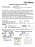
3 Qualified Personnel Qualified personnel are required to conduct the work described and recognize potential hazards. Recommended Installation for Optimal Performance A. B. 837T. C 1. a. Installation at angle pieces, against the direction of flow b. Installation in smaller pipes, inclined against the direction of flow c. Installation vertical to the direction of flow. Display Solid-state Temperature Switch Specifications Certifications CE conformity -EMC directive 2004/108/EC/,EN 61326 emission (group 1, class B), and interference immunity (industrial application). RoHs conformity - 2011/65/EU. Environment: Operating Conditions Ambient Temperature Range (1) -20 80 C (-4 +176 F).
4 Storage Temperature (1) -20 80 C (-4 +176 F). Vibration Resistance Probe Length <-150 mm ( in.): 6 g ( oz) (IEC 60068-2-6, under resonance). Probe Length >=250 mm ( in.): 2 g ( oz) (IEC 60068-2-6, under resonance). Operating Pressure 150 bar (2175 psi) maximum Shock Resistance 50 g ( oz) (IEC 60068-2-27, mechanical). Humidity 45 75 % r. h. Ingress Protection IP65 and IP67. The stated ingress protection (per IEC 60529) only applies when plugged in using mating connectors that have the appropriate ingress protection. Electrical Power Supply 15 35 V DC. Current Consumption Switching outputs with: Analog signal 4 20 mA; 70 mA;. Total Current Consumption Maximum 450 mA including switching current Outputs Output Type IO-Link - Version (Pin 4).
5 With the IO-Link option, switching output OUT 1 is always PNP. Zero Offset Adjustment Maximum 3% of span Output Thresholds OUT 1 and OUT 2 are individually adjustable Output Modes Selectable - Normally open, normally closed,window, hysteresis Output Voltage (Power Supply -1V). Output Current OUT1 maximum 100 mA, OUT2 maximum 250 mA. Load Analog signal 4 20 mA: k . Service Life 100 million switching cycles Response Time T05 < 5 s (per DIN EN 60751). T09 < 10 s (per DIN EN 60751). Accuracy Data Analog Signal of span Temperature sensor error Adjustment Accuracy Switching Points of span Scaling Analog Signal 0 25% of span Full scale: 75 100% of span Switching Output % of span Temperature sensor error Display of span Temperature sensor error 1 digit Temperature Error (2) K + t(3) per EN 60751 ( * ( + (t - 32) ).)
6 Reference Operation Conditions Temperature 15 25 C (59 77 F). Atmospheric Pressure 950 1,050 mbar ( psi). Humidity 45 75 % r. h. Nominal Position Process connection lower mount (LM). Power Supply 24V DC. (1). At high, medium, or ambient Temperature , helps ensure (by suitable measures) that the instrument case Temperature does not exceed 80 C (176 F) in continuous operation (the Temperature is measured hexagon of the process connection). At medium temperatures (above 80 C (176 F), the thread must not be immersed into the medium. (2). The achievable accuracy is determined by the mounting situation (immersion depth, sensor length, operating conditions). This is especially the case for large Temperature gradients between the environment and the medium.)
7 (3) Absolute value of Temperature . 2 Rockwell Automation Publication 837T-IN001A-EN-P - May 2016. Display Solid-state Temperature Switch Specifications (continued). Electrical Safety Short-circuit protection 4 20 mA, Out 1/Out 2 vs. V- Reverse polarity protection V+ vs. V- Insulation voltage 500V DC. Overvoltage protection 40V DC. Material Wetted Parts Temperature sensor Stainless Steel 316Ti Non-wetted Parts Housing Stainless Steel 304. Keyboard TPE-E. Display Window Polycarbonate Display Head PC + ABS-blend Measuring Ranges Temperature C F. Standard -20 +80 -4 +176. Dimensions [mm (in.)]. Attribute Description ( ). Measuring Element Pt1000, 2-wire, DIN EN 60751/Class A.
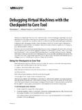
8 Application Measurement and monitoring of set temperatures Process Connection Thread 1/4 in. NPT male 36. 1/2 in. NPT male ( ). G 1/2 in. BSPP male G 1/4 in. BSPP male 821 M12x1. 35 ( ). 35 1. ( ) 35 1 ( ). dia. ( ). G 1/2 1/2 NPT. ( ) dia. 6. ( ). dia. 12 ( ). 13. ( ). G 1/4 1/4 NPT. ( ). 38. ( ) dia. 1. Dimensions are for reference only and are variable depending on the process connection. Rockwell Automation Publication 837T-IN001A-EN-P - May 2016 3. Display Solid-state Temperature Switch Process Connection [mm (in.)]. G Male NPT Male L1. L1. G. G. G L1 [mm (in.)] G L1 [mm (in.)]. G 1/4 12 ( ) 1/4 in. NPT 13 ( ). G 1/2 14 ( ) 1/2 in. NPT 19 ( ). Wiring Diagrams 1 PNP x 4 20 mA 2 PNP.
9 15 35V DC 15 35V DC. (+) 1 4 OUT1 (+) 1 4 OUT1. 2 3 (-) 2 3 (-). 4 20 mA OUT2. Mating Cables 889D F4AC-2 (M12x1 connector). 889D-R4AC-2 (M12x1 right angle connector). Output Signals Switching Output 1 Switching Output 2 Analog Signal PNP - 4 20 mA (3 wire). PNP PNP - Commissioning ATTENTION: Only for use with the Temperature Switch if it is in perfect condition concerning safety. Check the following points before commissioning: Leaking fluid is indicative of damage. Since this is a safety-relevant component, check the diaphragm for any visible damage. Required tool: Spanner size 27 open-ended spanner and screwdriver. Making the Mechanical Connection While mounting, make sure that the sealing faces at the instrument are clean and undamaged.
10 Only screw in or unscrew the instrument via the spanner flats. Never use the case as a working surface. The correct torque depends on the dimensions of the process connection and the gasket used (form/material). When screwing in, be careful not to cross the threads. 4 Rockwell Automation Publication 837T-IN001A-EN-P - May 2016. Display Solid-state Temperature Switch Types of Sealing For cable outlets, make sure that no moisture enters at the cable end. Figure 1 - Parallel ThreadTapered Thread (NPT). per EN 837 per DIN 3852-E Dismantle and Disposal Dismantle: Let the instrument cool down sufficiently before dismantling. ATTENTION: Residual media in the dismantled Temperature transmitter can result in a risk to persons, the environment, and equipment.