Transcription of DISSOLVED GAS ANALYSIS OF MINERAL OIL INSULATING …
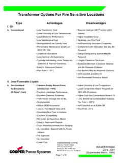
1 Northern Technology & Testing 8140 Industrial Parkway, Suite 8 Sacramento, CA 95824 Tel: (916) 383-6800 Fax: (916) 383-7794 DGA EXPERT SYSTEMS A leader in quality, value & DISSOLVED GAS ANALYSIS OF MINERAL OIL INSULATING FLUIDS Written by: Joseph B. DiGiorgio, Dr. DiGiorgio conducts seminars on request. 1996-2005 NTT Copyrighted material. Contact Dr. DiGiorgio INSULATING materials within transformers and related equipment break down to liberate gases within the unit. The distribution of these gases can be related to the type of electrical fault and the rate of gas generation can indicate the severity of the fault. The identity of the gases being generated by a particular unit can be very useful information in any preventative maintenance program. This technique is being used quite successfully throughout the world. This paper deals with the basics underlying this technique and deals only with those INSULATING fluids of MINERAL oil origin. Obvious advantages that fault gas analyses can provide are: 1.
2 Advance warning of developing faults 2. Determining the improper use of units 3. Status checks on new and repaired units4. Convenient scheduling of repairs 5. Monitoring of units under overload The following sections will deal with the origins of the fault gases, methods for their detection, interpretation of the results,and philosophies on the use of this technique. Some limitations and considerations that should be kept in mind concerning the use of this technique will also be discussed. Finally an appendix containing some actual case histories will be covered. Fault Gases The causes of fault gases can be divided into three categories; corona or partial discharge, pyrolysis or thermal heating, and arcing. These three categories differ mainly in the intensity of energy that is dissipated per unit time per unit volume by the fault. The most severe intensity of energy dissipation occurs with arcing, less with heating, and least with corona. Northern Technology & Testing 8140 Industrial Parkway, Suite 8 Sacramento, CA 95824 Tel: (916) 383-6800 Fax: (916) 383-7794 DGA EXPERT SYSTEMS A leader in quality, value & A partial list of fault gases that can be found within a unit are shown in the following three groups: 1.
3 Hydrocarbons and hydrogen Methane CH4 Ethane C2H6 Ethylene C2H4 Acetylene C2H2 Hydrogen H2 2. Carbon oxides Carbon monoxideCO Carbon dioxide CO2 3. Non-fault gases NitrogenN2 Oxygen O2 These gases will accumulate in the oil, as well as in the gas blanket of those units with a headspace, as a result of various faults. Their distribution will be effected by the nature of the INSULATING materials involved in the fault and the nature of the fault itself. The major (minor) fault gases can be categorized as follows by the type of material that is involved and the type of fault present: 1. Corona a. Oil H2 b. Cellulose H2 , CO , CO2 2. Pyrolysis a. Oil Low temperature CH4 , C2H6 High temperature C2H4 , H2 ( CH4 , C2H6 ) b. Cellulose Low temperature CO2 ( CO ) High temperature CO ( CO2 ) 3. Arcing H2, C2H2 (CH4, C2H6, C2H4) MINERAL oil INSULATING fluids are composed essentially of saturated hydrocarbons called paraffins, whose general molecular formula is CnH2n+2 with n in the range of 20 to 40.
4 The cellulosic insulation material is a polymeric substance whose general molecular formula is [C12H14O4(OH)6]n with n in the range of 300 to 750. Northern Technology & Testing 8140 Industrial Parkway, Suite 8 Sacramento, CA 95824 Tel: (916) 383-6800 Fax: (916) 383-7794 DGA EXPERT SYSTEMS A leader in quality, value & The structural formula of the MINERAL oil and those of the hydrocarbons and hydrogen fault gases are shown in Figure 1. Figure 1. Structure of INSULATING oil and fault gases. MINERAL Oil CnH2n+2 Hydrogen H2 Methane CH4 Ethane C2H6 Ethylene C2H4 Acetylene C2H2 Carbon Dioxide CO2 Carbon MonoxideCO Oxygen O2 Nitrogen N2 Northern Technology & Testing 8140 Industrial Parkway, Suite 8 Sacramento, CA 95824 Tel: (916) 383-6800 Fax: (916) 383-7794 DGA EXPERT SYSTEMS A leader in quality, value & Figures 2, 3, 4, and 5 illustrate the processes occurring with corona, pyrolysis, and arcing in oil and pyrolysis of cellulose respectively. Typical fault gas distributions are also shown.
5 Figure 2. Corona in Oil H2 88% C02 1 C0 1 CH4 6 C2H6 1 C2H4 C2H2 Figure 3. Pyrolysis in Oil H2 16% C02 trace C0 trace CH4 16 C2H66 C2H441 C2H2trace Figure 4. Arcing in Oil H2 39% C02 2 C0 4 CH4 10 C2H4 6 C2H2 35 Figure of Cellulose H2 9% C02 25 C0 50 CH4 8 C2H4 4 C2H2 Northern Technology & Testing 8140 Industrial Parkway, Suite 8 Sacramento, CA 95824 Tel: (916) 383-6800 Fax: (916) 383-7794 DGA EXPERT SYSTEMS A leader in quality, value & The solubilities of the fault gases in MINERAL oil as well as their temperature dependence are also important factors for consideration in fault gas analyses.
6 Table 1 lists the saturation solubilities for the fault gases. It should be noted that there is almost two orders of magnitude difference. Table of Gases in Transformer Oil. Static Equilibrium at 760 mm Hg and 25oC. Hydrogen 7 % by volume Nitrogen % Carbon monoxide 9 % Oxygen 16 % Methane 30 % Carbon dioxide 120 % Ethane 280 % Ethylene 280 % Acetylene 400 % between the least soluble (hydrogen) and the most soluble (acetylene) gas. The majority of gases that are indicative of faults are also those that are in general the more soluble in the oil.
7 When rates of gas generation are being followed it is important to take into account the solubilities of these gases as a function of the oil temperature (Fig. 6). Over a temperature range of 0 to 80oC some gases increase in solubility up to 79% while others decrease their solubility up to 66%. Northern Technology & Testing 8140 Industrial Parkway, Suite 8 Sacramento, CA 95824 Tel: (916) 383-6800 Fax: (916) 383-7794 DGA EXPERT SYSTEMS A leader in quality, value & Figure 6. Relative Solubilities as a Function of Temperature. Northern Technology & Testing 8140 Industrial Parkway, Suite 8 Sacramento, CA 95824 Tel: (916) 383-6800 Fax: (916) 383-7794 DGA EXPERT SYSTEMS A leader in quality, value & Methods of Fault Gas Detection Three methods will be discussed and their advantages and disadvantages will be compared. The first method and probably the most widely used technique at the present time is the one that determines the total combustible gases ( TCG ) that are present in the gas above the oil.
8 The major advantage of the TCG method compared to the others that will be covered is that it is fast and applicable to use in the field. In fact it can be used to continuously monitor a unit. However, there are a number of disadvantages to the TCG method. Although it detects the combustible fault gases (hydrogen, carbon monoxide, methane, ethane, ethylene, and acetylene), it does not detect the noncombustible ones (carbon dioxide, nitrogen, and oxygen). This method is only applicable to those units that have a gas blanket and not to the completely oil-filled units of the conservator type. Since most faults occur under the surface of the oil, the gases must first saturate the oil and diffuse to the surface before accumulating in the gas blanket above the oil. These processes take time, which delays the early detection of the fault. The major disadvantage of the TCG method is that it gives only a single value for the percentage of combustible gases but does not identify which gases are actually present.
9 It is this latter information that is most useful in determining the type of fault that has occurred. The second method for the detection of fault gases is the gas blanket ANALYSIS in which a sample of the gas in the space above the oil is analyzed for its composition. This method detects all of the individual components; however, it is also not applicable to the oil-filled conservator type units and it also suffers from the disadvantage that the gases must first diffuse into the gas blanket. In addition, this method is not at present best done in the field. A properly equipped laboratory is preferred for the required separation, identification, and quantitative determination of these gases at the part per million level. The third and most informative method for the detection of fault gases is the DISSOLVED gas ANALYSIS ( DGA ) technique. In this method a sample of the oil is taken from the unit and the DISSOLVED gases are extracted. Then the extracted gases are separated, identified, and quantitatively determined.
10 At present this entire technique is best done in the laboratory since it requires precision operations. Since this method uses an oil sample it is applicable to all type units and like the gas blanket method it detects all the individual components. The main advantage of the DGA technique is that it detects the gases in the oil phase giving the earliest possible detection of an incipient fault. This advantage alone outweighs any disadvantages of this technique. Northern Technology & Testing 8140 Industrial Parkway, Suite 8 Sacramento, CA 95824 Tel: (916) 383-6800 Fax: (916) 383-7794 DGA EXPERT SYSTEMS A leader in quality, value & Methods of Interpretation The most important aspect of fault gas ANALYSIS is taking the data that has been generated and correctly diagnosing the fault that is generating the gases that have been detected. Several methods that are currently in use will be covered. One of the earliest methods is that of Dornenburg3 in which two ratios of gases are plotted on log-log axes (Fig.)