Transcription of DIVISION III STANDARD DRAWINGS EROSION & SEDIMENT …
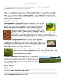
1 EROSION & SEDIMENT CONTROLDIVISION III STANDARD DRAWINGSNUMBER ESC-TCTABLE OF CONTENTSCOVER PAGE / STANDARD DRAWINGADOPTED:AMERICAN PUBLIC WORKS ASSOCIATIONMETRO CHAPTERKANSAS CITY10/24/2016 Existing GroundNon-Woven Geotextile5:1 Existing PavementMountable Berm (Optional)Side ElevationNot to ScaleCONSTRUCTION ENTRANCE50' " ' ' 10' ' Min.(Optional)Washrack / Rumble Strip50' GroundSediment Trapping DevicetoPositive drainage ingress and egress operation* - Must extend full width of Aggregate2-3" Coarse20' Geotextile3" " ViewNot to ScaleSection A-ANot to Scale3'CONCRETE WASHOUT sides of the subsurface pit in sandy or gravelly A one-piece impervious liner may be required along the bottom andand pump the concrete washout area(s) to operators of concrete truckarea and elsewhere as necessary to clearly indicate the location(s)Signs shall be placed at the construction site entrance, washout tracking control is required at the access point to shall be sloped towards the concrete washout area.
2 Leading out of the subsurface pit shall be 3:1. The vehicle trackingrelative to the amount of concrete to be placed on site. The slopesConcrete washout area shall include a flat subsurface pit on washout areas shall be installed prior to any material Shallbe used for perimeter for berm Shall becompacted in the samemanner as trench Fence (optional)Vehicle TrackingControlSlope3:14:1 City of Great Bend STANDARD DRAWINGS . for EROSION and SEDIMENT control ; Concrete Washout modified from 2009 Construction Entrance modified from 2015 Overland Park STANDARD Details* the graded foundation to improve If conditions warrant, place geotextile fabric on a SEDIMENT control Divert all surface runoff and drainage from the entrance to Leave surface sloped for Place stone to dimensions and grade as shown on plans.
3 Drainage ditches along public Install pipe under the entrance if needed to maintain public road to divert runoff from it. foundation approximately 15 feet from the edge of the 6- to 8-inch high ridge with 3H:1V side slopes across the3. If slope towards the public road exceeds 2%, construct a the foundation area, grade, and crown for positive Remove all vegetation and other unsuitable material from downhill of disturbed locating on steep slopes, at curves on public roads, or1. Notes for Construction Entrance:Maintenance for Construction Entrance:1. Reshape entrance as needed to maintain function and integrity of Installation. Top dress with clean aggregateas for Concrete Washout:Maintenance for Concrete Washout.
4 Concrete washout areas shall be with the installation, maintenance, and/or removal of thewith suitable compacted backfill and topsoil, any disturbed areasWhen concrete washout areas are removed, excavations shall be project is washout areas shall remain in place until all concrete a water-tight container and disposed of in the subsurface pit shall be transported from the job siteConcrete washout water, wasted pieces of concrete and all for wasted washout areas shall be enlarged as necessary to filled the washout to approximately 75% washout materials shall be removed once the ESC-01 AND CONCRETE WASHOUTCONSTRUCTION ENTRANCESTANDARD DRAWINGADOPTED:AMERICAN PUBLIC WORKS ASSOCIATIONMETRO CHAPTERKANSAS CITY10/24/20168" overlap4" on centerSlope6" " of ErosionControl BlanketNot to Scale15' Min.
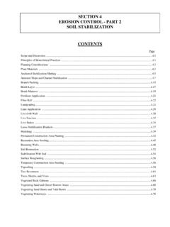
5 * (where directed by the plans) permanent slope protection is immediately covered by may be omitted if the areaErosion control Blanket or TRM - *12" " " " Overlaps and seams;- Projected water line;- Channel bottom / side slope vertices;ABCI nstallation Around Culvert SlopeInstallation on SlopesSplice SeamSplice SeamLongitudinal SeamAnchor FoldAnchor SlotLongitudinal SeamEdge AnchorV ChannelTrapezoidal ChannelCritical Points:Partial Box Culvert PlanInstallation in Channels with anchors 9 inches apart. turned under a minimum of 4 inches, then anchored in place4. TERMINAL FOLD: The bottom edge of the blanket shall be seams. minimum of 8 inches in direction of water flow. Stagger splice3.
6 SPLICE SEAM: When splices are necessary, overlap end a then backfilled, tamped and seeded. deep with the blanket anchored in the bottom of the slot, inches apart. The slots should be 6 inches wide x 6 inches at the top of the slope and anchored in place with anchors 62. ANCHOR SLOTS: The top of the blanket should be "slotted in" with the soil , lay blanket loosely, avoiding stretching. direction of the slope. In order for blanket to be in contact1. EROSION control Blankets and TRMs shall be laid in theNotes for Installation on Slopes:catching the edges of both each other a minimum of 6 inches, with anchorsLONGITUDINAL SEAMS: The edges of the blanket or mat the manufacturers anchors and pattern/spacing shall be installed according2.
7 Referenced to select type of blanket or mat to be Specifications 2150 and Design Guidance 5100 shall TERMINUS: The bottom edge of the mat shall be anchored. of the slope and EDGE ANCHORS: Lay outside edge of mat into trench at top shall then cover the slot and be anchored as shown. and buried similar to the edge anchor fold. The upstream mat The top of the downstream mat shall be slotted in, secured The mat shall be cut to a length 12 inches beyond the slot. 30 feet. The slots should be 6 inches wide x 6 inches CHECK SLOTS: Establish check slots transverse to slope every splice seams. minimum of 12 inches in direction of water flow. Stagger3. SPLICE SEAM: When splices are necessary, overlap end a the top as shown in detail.
8 The bottom of the slot, backfilled, and the mat folded over buried in a slot 6 inches wide x 6 inches deep, anchored in placed 6 inches apart. The top edge of the mat should be buried and secured with wood or other approved anchors2. ANCHOR FOLD: The top of the mat should be folded under, contact with the soil , lay the mat loosely, avoiding stretching. of channel, where applicable. In order for the mat to be in direction of the flow, with the first course at the centerline1. EROSION control Blankets and TRMs shall be laid in theNotes for Installation in Channels:for EROSION and SEDIMENT from 2015 Overland Park STANDARD DetailsGeneral Notes:Maintenance:1. Torn or degraded product shall be repaired or replaced, unless such degradation is within the functional longevity specified by the manufacturer.
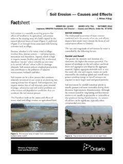
9 2. Edges or seams that are loose or frayed shall be ESC-02 AND TURF REINFORMENT MATSEROSION control BLANKETSSTANDARD DRAWINGADOPTED:AMERICAN PUBLIC WORKS ASSOCIATIONMETRO CHAPTERKANSAS CITY10/24/2016 Backfilled trench2' of Flow FLOWPOSTS(*) SILT FENCE DETAILSNot to Scaleat 4' max spacing4' min length post(See Note 6.)Post embedment2' compaction zone3' wideGeotextile fabricfastened to the of 6" which has been between 9 and 14 and max. mesh wire fencing with min. wire gauge material can be attached to woven For additional strength filter fabric Posts (*) at 4' Max. spacing- STEEL LB/FT"85" x 2 85- SOUTHERN PINE 2 "163" x 1 163- HARDWOOD 1 - MIN, LENGTH 4'Material (**)Filter fabric of AASHTO M288 meet the requirements(**) - Geotextile Fabric shall(50 lb tensile strength) located in top 8"approved by the field engineer,Staples, plastic zip ties or other material 6" - 12" depthMachine sliceFigure AIncorrect980978976982980978982 FlowStreetStreetStreetStreet100' Maximum Runs (Typ.)
10 Silt FenceUphill (Typ)Ends Turned SILT FENCE LAYOUTNot to Scale6' - 10'Flowsediment storage ' to 10' away from the toe to create a to slow velocity and volume of water and nstall silt fence at the top of the slope I976 FlowCorrectSilt fence postOverlap filter fabric between postsJOINING FENCE SECTIONS staples or plastic zip tiesattach to the post with Wrap filter fabric around and Not to ScaleSilt Fence 18" Minimum used. installation, where slicing machine cannot be reasonably6. Trenching will only be allowed for small or difficult5. Install posts a minimum of 2' into the ground. 4. Attach fabric to upstream side of post. of silt fence to slow runoff Long slopes should be broken up with intermediate rows (Figure A).