Transcription of DMP catalogue 1-200 kW, 5-1000 Nm - T-T Electric
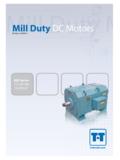
1 DMP catalogue1-200 kW, 5-1000 NmDC MotorsIntroduction ..Options ..Application data ..Output data ..Dimension drawings, IC06 ..Dimension drawings, IC17/37 ..Dimension drawings, IC666 ..Dimension drawings, IC86W ..Dimensions, flanges ..Order form ..p. 3p. 4p. 5p. 7p. 31p. 33p. 34p. 35p. 36p. 37 List of contentsBasic design characteristicsFully laminated stator, mainpoles and square installation of openings in end shields for easy windings of varnishinsulated copper armature core ofhigh grade insulated number of coolingducts in armature provideexcellent armature lamina-tions for low torque windings of var-nished copper designed forlow commutating stressesand high is impregnated toensure high degree of motors are fullylaminated, 2 or 4 pole, : 1-200 kWTorque: 5-1000 NmDMP motor range:Type designation example :DMP 180-4 EDM= DC motorP= Motor type180= Centre height in mm4= Number of polesE= Core length3 IntroductionBrush holders with springloaded pressure for a number ofoptions and accessoriesensuring high with excellent corro-sion resistant with IEC as NEMA approved.
2 Frame sizeDMP112-2112-4132-2132-4160-4180-4 CorelengthsMA, LAM, LMS, M, L, LBS, SO, M, MO, L, LO, LBA, B, C, D, E, FFrame sizeDMP112-2112-4132-2132-4160180 Cooling formsIC06(IP23)Force ventilatedIC17(IP23)Single pipe ventilatedIC37(IP54)Double pipe ventilatedIC410 (IP54)Totally enclosedIC416 (IP54)Totally enclosed, fan cooledIC666 (IP54)Air-air cooledIC86W (IP54)Air-water cooledOther cooling forms availableProtectionIP55 Mounting formsIM1001 Horizontal footIM1002 Horizontal foot, two shaft endsIM2001 Horizontal foot and flangeIM2011 Vertical foot and flangeOther mounting forms availableModifications and accessoriesCompound windingPressure switchTemperature sensor, interpoleTemperature sensor, field windingBearing sensorGrounding brushHeating elementBrush wear sensorSpecial shaftRoller bearing d-endShaft seal, d-endSpecial balance Class R Special paint (RAL colour)Special corrosion protectionTransparent inspection coverBrakeGearboxTachos with couplingREO 444R1 (60v/1000min-1)TDP LT-4 (60v/1000min-1)Others availablePulse generatorsPOG 9 D (1-1250 ppr)HG650 or DG60L (1024 ppr)Others available4 Optionsooooooooooooooooooooooooooooooooo oooooooooooooooooooooooooooooooooooooooo oooooooooooooooooooooooooooooooooooooooo oooooooooooooooooooooooooooooooooooooooo oooooooooooooooooooooooooooooooooooooooo ooooooooo5 Application dataStandardsIEC 34 - IEC 72 HTemperature riseClass F BalanceIEC 34-14 grade 'N' 'R' on capacity180% xFLC for 15 sec.
3 Every 5 minutes30 sec. every 30 minutesTerminal boxStandard position: On right handside (facing D-end).Mounting of terminal box on topor left hand side on motors are delivered witha large terminal box IP55 includ-ing knockout openings:DMP 112 1322 x (PG 21)2 x (PG )Cable entry from Drive 160 1802 x 55 (PG 42)4 x (PG 21)Cable entry from above positionStandard: On top of the motor atthe non-drive positions on is supplied without filteras on lubricated ball bearingsas belt drive please contact oursales exchangersAir/water (IC86W):Air/water exchangers are espe-cially recommended for is for clean corrosive water on on top of the motor asstandard. Fan motor at connection flanges at right hand side (facing D-end).Max. water pressure 10 PSIMax. inlet water water temperature rise of 8-100 Cmust be motors with low loads or alow incoming water temperature,a temperature regulator isrecommended to avoid conden-sation in the cooling air circuitand to minimize water constant speed fan circulatesthe internal cooling air.
4 A polya-mide filter is provided for (IC666):Air/air heat exchangers arerecommended where water isnot available for cooling output of a motor withair/air exchanger will be approxi-mately 20% lower compared tocooling forms IC06/17/37 : On top of the motor constant speed fans at topof the heat exchanger to provideair circulation for the outer andinner heat exchanger information on blower motor dataDMPUnet,fnet(Y)IY(A)Unet,fnet( )I (A)Pfan(kW)Wfan(kg)1123x380-420 V. 50 V. 50 V. 60 V. 60 V. 50 V. 50 V. 50 V. 60 V. 60 V. 50 V. 50 V. 50 V. 60 V. 60 V. 50 V. 50 V. 50 V. 60 V. 60 V. 50 V. 50 V. 50 V. 60 V. 60 V. 50 , fnet(Y)Supply voltage, frequency YIYC urrent YPfanPowerUnet, fnet( )Supply voltage, frequency I Current WfanTotal fan weightBearingsDrive endNon-drive endDMPBall bearingRoller bearing1126308-C3NU 308 ECP6208-2RS 1-HT-C31326309-C3NU 309 ECP6307-2RS 1-HT-C31606310-C3NU 310 ECP6309-2RS 1-HT-C3180-4A/B/C/D/E6215-C3NU 2215-ECP6312-2RS1-HT-C3180-4F6315-C3NU 315 ECP6312-2RS1-HT-C3 Application data7 Select motor frame size againstvoltage, output and speed.
5 Forintermediate output, take thenearest higher output listedunder the next frame size. Forintermediate speed take thenext lower speed listed withinthe output required. The outputlists are based on: Cooling formsIC06/IC17/IC37/IC86W. The armature circuit resis-tance listed is for dutywarm condition. The inductance listed is for the armature circuit. Motor supply from 3-phasefully controlled power/constant torqueThe full field or base speed andmaximum speed through fieldcontrol with constant output islisted for each voltage: For -10% theoutput and speed are proportio-nal to the higher shunt field ranges,please refer to sales a combination of armaturevoltage/shunt control greaterconstant power ranges can cyclesRatings: All outputs are dutytype S 1 and motors are fedfrom a 3-phase fully controlledthyristor where the form factor is windingsAll motors in the output listshave separate excitation, thefield being shunt winding can be supplied on with compound windingmay have nominal data whichdiffer from those shown in theoutput voltageFor other armature voltages,please contact our sales temperature and altitudeOutputs in this catalogue arebased on max.
6 400 Cambienttemperature and motor locatedat max. 1000 metres above ambient temperature and/oraltitude is higher, contact oursales output dataNEMA catalogue available motorsMotors indicated with the sign in the output data lists areavailable from stock and can be delivered stock motors are availableaccording to following specifica-tion. Motor fan, standard tacho-generator and coupling can befitted on request. IM 1001, IP 23, IC 17, desig-ned for cooling air inlet ateither D or N-end (whenpossible, cooling air inletshould always be at the D-end of DMP motors). Cylindrical roller bearing onD-end. Terminal box on right handside (facing D-end). Balanced with half key. Thermostats NC. PTC thermistors. Name plate and documentsin English. Rating data as standardmotors but field weakeningis only allowed up to 25 %overspeed for stockmotors. Stock motors have a paral-lel /serial connection sui-table for an excitation volta-ge of 170-180-190/340-360-380 V. Stock motors have reinfor-ced data8 Technical datanmaxn0 JPfUamaxUfVcoolPrW(foot)W(flange)nmaxMax mechanical speedn0 Min speed at constant torqueJMoment of inertiaPfExcitation powerUamaxMax rated voltageUfExcitation voltageVcoolCooling air flowPrStatic pressure drop (IC17, IC37)W(foot)Weight: foot mounting *W(flange)Weight: flange mounting **excl.
7 AccessoriesCat. Nr Ua(V): 400420440470520550 PIThn2RA(115 C)LA(0Hz)FR (min-1)(kW) (A) (Nm)(%)min-1( )(mH)nbBase speedUaArmature voltagePMechanical powerIArmature currentTTorquehEfficiency IECn2 Max electrical speedRAArmature resistanceLAArmature inductance Data subject to change without prior data930 NmData subject to change without prior datanmaxn0 JPfUamaxUfVcoolPrW(foot)W(flange) * Nr Ua(V):260400420440470520 PIThn2RA(115 C)LA(0Hz)FR (min-1)(kW) (A) (Nm) (%)min-1( )(mH)5000 min-140 min-1 kgm2 420 W 620 V 110-440 V 235 m3/h 375 Pa 90 kg 102 kg 1 Cooling air inlet at commutator side. Can be used with cooling air inlet at shaft side with 10% reduction of power.* Normally kept in stock with reinforced subject to change without prior Nm112-2 LATechnical datanmaxn0 JPfUamaxUfVcoolPrW(foot)W(flange) * * * Nr Ua(V):260400420440470520 PIThn2RA(115 C)LA(0Hz)FR (min-1)(kW) (A) (Nm) (%)min-1115 C ( )(mH)5000 min-140 kgm2500 W620 V110-440 V235 m3/h375 Pa96 kg108 kg 1 Cooling air inlet at commutator side.
8 Can be used with cooling air inlet at shaft side with 10% reduction of power.* Normally kept in stock with reinforced subject to change without prior Nm112-4 MTechnical datanmaxn0 JPfUamaxUfVcoolPrW(foot)W(flange) Nr Ua(V):260400420440470520 PIThn2RA(115 C)LA(0Hz)FR (min-1)(kW) (A) (Nm) (%)min-1115 C ( )(mH)5000 min-140 kgm2625 W550 V110-440 V270 m3/h480 Pa103 kg115 kg 1 Cooling air inlet at commutator side. Can be used with cooling air inlet at shaft side with 10% reduction of power.* Normally kept in stock with reinforced subject to change without prior Nm112-4 LTechnical datanmaxn0 JPfUamaxUfVcoolPrW(foot)W(flange) * * * * Nr Ua(V):260400420440470520 PIThn2RA(115 C)LA(0Hz)FR (min-1)(kW) (A) (Nm) (%)min-1115 C ( )(mH)5000 min-140 kgm2740 W550 V110-440 V270 m3/h480 Pa110 kg122 kg1 Cooling air inlet at commutator side. Can be used with cooling air inlet at shaft side with 10% reduction of power.* Normally kept in stock with reinforced impregnation.
9 13 Data subject to change without prior Nm132-2 MTechnical datanmaxn0 JPfUamaxUfVcoolPrW(foot)W(flange) Nr Ua(V):260400420440470520 PIThn2RA(115 C)LA(0Hz)FR (min-1)(kW) (A) (Nm) (%)min-1115 C ( )(mH)5000 min-140 kgm2550 W620 V110-440 V435 m3/h400 Pa132 kg147 kg1 Cooling air inlet at commutator side. Can be used with cooling air inlet at shaft side with 10% reduction of power.* Normally kept in stock with reinforced impregnation. Data subject to change without prior Nm132-4 STechnical datanmaxn0 JPfUamaxUfVcoolPrW(foot)W(flange) * * Nr Ua(V):260400420440470520 PIThn2RA(115 C)LA(0Hz)FR (min-1)(kW) (A) (Nm) (%)min-1115 C ( )(mH)4000 min-140 kgm2750 W620 V110-440 V470 m3/h550 Pa115 kg130 kg1 Cooling air inlet at commutator side. Can be used with cooling air inlet at shaft side with 10% reduction of power.
10 * Normally kept in stock with reinforced impregnation. 15 Data subject to change without prior Nm132-4 MTechnical datanmaxn0 JPfUamaxUfVcoolPrW(foot)W(flange) * * Nr Ua(V):260400420440470520 PIThn2RA(115 C)LA(0Hz)FR (min-1)(kW) (A) (Nm) (%)min-1( )(mH)4000 min-140 kgm2830 W620 V110-440 V470 m3/h550 Pa145 kg160 kg1 Cooling air inlet at commutator side. Can be used with cooling air inlet at shaft side with 10% reduction of power.* Normally kept in stock with reinforced impregnation. 150 Nm132-4 LTechnical datanmaxn0 JPfUamaxUfVcoolPrW(foot)W(flange) * * * Nr Ua(V):260400420440470520 PIThn2RA(115 C)LA(0Hz)FR (min-1)(kW) (A) (Nm) (%)min-1( )(mH)4000 min-140 kgm21000 W620 V110-440 V470 m3/h550 Pa170 kg185 kg1 Cooling air inlet at commutator side.