Transcription of DOE/NASA Advances in Liquid Hydrogen Storage Workshop
1 DOE/NASA Advances in Liquid Hydrogen Storage Workshop Virtual, Wednesday August 18th , 2021 Overview of the New LH2 Sphere at NASA Kennedy Space Center James E. Fesmire and Adam Swanger Sr. Principal Investigator NASA Kennedy Space Center, Cryogenics Test Laboratory, KSC, FL 32899 USA 1 Highlights World s largest LH2 Storage tanks constructed in mid-1960s at NASA Kennedy Space Center in Florida by Chicago Bridge & Iron These vacuum-perlite insulated tanks, still in service, are 3,200 m3 capacity (ea.) In 2019, CB&I Storage Solutions (CB&I) began construction of additional 4,700 m3 LH2 Storage tank at LC-39B NASA s new Space Launch System (SLS) heavy lift rocket for Artemis program holds 2,033 m3 of LH2 in its flight tank New energy-efficient technologies implemented: passive + active control: Evacuated glass bubbles insulation system has been shown to reduce LH2 boiloff by 46% versus perlite in field demonstrations Internal tank heat exchanger to enable controlled Storage via IRAS.
2 Ullage pressure control, zero boiloff, zero-loss transfer, and/or densification 2 History of large-scale Storage Launch Complex 39 (LC-39) A & B built in 1960 s for Apollo moon program Identical layout Cryogenic Storage systems sized for Apollo missions (Saturn V vehicle) Both used throughout Apollo and Space Shuttle Programs LC-39B now for Artemis program LC39 B LC39 A LO2 LH2 3 4 site-built tanks for LO2 & LH2 Constructed 1963-1965 by Chicago Bridge & Iron Co. Designed for Normal Boiling Point (NBP) Storage 4 LC-39 CRYOGENIC Storage APOLLO ERA Saturn V Weight = Mlbs Thrust = Mlbs Total On-Board Cryo Prop. LO2 = 454 Kgal, LH2 = 335kgal Liquid Oxygen (2 ea.)
3 900,000 gal (3,407 m3) useable volume ~69 ft. (21 m) outer diameter; MAWP = 12 psig ( bar) Double-walled w/perlite bulk-fill insulation (~4 ft. thick), purged with nitrogen gas (no-vacuum) Normal Evaporation Rate = (900 gal/day) 1965 CRYO Storage TANK SPECIFICATIONS Liquid Hydrogen (2 ea.) 850,000 gal (3,218 m3) useable volume ~69 ft. (21 m) outer diameter; MAWP = 90 psig ( bar) Evacuated perlite bulk-fill insulation (~4 ft. thick) Normal Evaporation Rate = (530 gal/day) Largest active LH2 tanks in the now! 5 1955 1965 2021 and Beyond Head start provided by the Atomic Energy Commission around 1955 for LH2 industrial -type development NASA went from a two m3 LH2 Storage tank to a pair of 3,200 m3 tanks by 1965 Built by Chicago Bridge & Iron Storage under contract w/ Catalytic Construction Co.
4 , these two are still the world s largest LH2 Storage tanks (and still in service today) NASA s new Space Launch System (SLS) heavy lift rocket for the Artemis program includes an LH2 flight tank holding 2,033 m3 of LH2 in its dia. by 40-m height SLS Assembly in VAB at KSC 6 INTRODUCTION In 2018, construction began on an additional LH2 Storage tank at Launch Complex 39B This new tank will give an additional Storage capacity of 4,732 m3 Total on-site Storage capacity of about 8,000 m3 NASA Kennedy Space Center s Launch Complex 39 7 OLD & NEW OVERALL CONCEPT FOR LH2 Storage AREA AT LC-39B New 4,700-m3 LH2 Storage tank Apollo-era 3,200-m3 LH2 Storage tank 8 Scale comparison of new 4,700-m3 Storage tank (left) and Apollo-era 3,200-m3 tank (right)
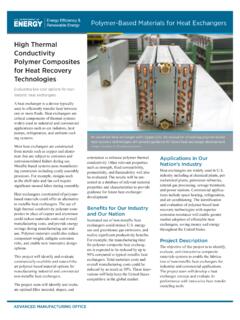
5 Tank specifications Detailed design and construction by CB&I Storage Tank Solutions as part of the PMI contract for the launch facility improvements ASME BPV Code Section XIII, Div 2 and ASME for piping Usable capacity = 4,732 m3 (1,250,000 gal) w/ min. ullage volume 10% Max. boiloff or NER of (600 gal/day, 2,271 L/day) Min. Design Metal Temperature (MMDT) = 4 K (-452 F) Pressure rating or Max. Allowable Working Pressure (MAWP) = full vacuum to barg (90 psig) or bard (105 psid) 10 Tank Configuration The outer diameter spherical tank has 15 support legs welded to the equator and stands at an overall height of m Tank is supplied from a tanker manifold and ambient air vaporizers for pressurization Tank includes a vent stack on top for normal boiloff gas and is connected to a dedicated facility flare stack of diameter Other standard piping nozzles include a 300-mm diameter vacuum-jacketed (VJ) Liquid withdrawal lines 11 Tank Design Total heat load (QT)
6 To the inner vessel is the combination of the thermal insulation system (evacuated), the structural support system, and the piping penetrations Three key ingredients of LH2 tank thermal performance : evacuated insulation (left); structural supports (middle); and piping penetrations (right) 12 LH2 Storage Tank 13 Usable capacity = 4,732 m3 (1,250,000 gal) Outer Dia. = 24-m (79-ft) MAWP = Full Vacuum to barg (90 psig) or bard (105 psid) New Technologies Integrated Refrigeration and Storage (IRAS) heat exchanger Glass Bubbles thermal insulation system (evacuated) Passive + Active = Full Control Cryogenics 14 New Technologies Two new energy-efficient technologies to provide large-scale LH2 Storage and control capability Passive thermal control: the glass bubbles insulation system (evacuated) is implemented in lieu of the perlite powder system which has been the mainstay in large-scale tanks for nearly 100 years Active thermal control.
7 Internal heat exchanger is implemented for the future addition of IRAS system for complete controlled Storage capability Passive-only no active control [Image: National Museum of American History] 15 New Technologies Part I Integrated Refrigeration and Storage (IRAS) Heat Exchanger 16 IRAS HEAT Exchanger Concept Traditional Storage tank -no control. Heat energy from ambient stores within the Liquid , ullage pressure rises, relief valve opens to vent. IRAS tank full control. Pressure and temperature are controlled by taking up the heat through the internal heat exchanger. No venting of boiloff gas. 17 IRAS HEAT Exchanger Design Upper and lower heat exchanger (HX) manifolds Positioned at the 25% and 75% fill level elevations Constructed of fully welded 38-mm ( OD) 316L stainless steel tubing Total coil length = 43 m, for a heat exchange area of ~ m2 Helium refrigerant will be fed to the coils via 51-mm (2-inch NPS), 304L stainless steel piping routed through the lower annulus One inlet.
8 One outlet Bayonet connections and isolation valves provided for inlet and outlet flexible VJ lines to connect to a refrigeration system 18 IRAS HEAT Exchanger Configuration Top manifold and support tower being lifted into place Heat exchanger configuration inside the sphere (left); 3D view of refrigerant feedlines and manifold (right) 19 New Technologies Part II Glass Bubbles Thermal insulation System 20 Glass Bubbles Development Timeline c1970 Accidental production of first glass bubbles at 3M plant in Guin, AL c1975 Cryogenic research testing by G. R. Cunnington and C. L. Tien at UC Berkeley 1998 Initial cryostat testing and research of glass bubble products by NASA/KSC Cryogenics Test Laboratory (CTL) 2003 Proposal to National Rocket Propulsion Technology Development Board, NASA Stennis Space Center, Glass Bubbles Retrofit of Perlite Insulated Cryogenic Storage Tanks 2003 NASA/HQ Office of Space Flight (OSF) IR&D Proposal, New Materials & Technologies for Cost-Efficient Cryogenic Storage & Transfer (CESAT) by CTL (start of major project with national academic-industry team) 2003 NASA SBIR Phase I, Cryogenic Propellant insulation Project, Technology Applications Inc.
9 (TAI) 2005 Field demonstration of 6000-gallon LN2 tank insulation system at Acme Cryogenics in Allentown, PA (TAI, SBIR) 2007 Completion of CESAT project and presentation of six papers at the Cryogenic Engineering Conference in Chattanooga, TN for publication in Advances in Cryogenic Engineering 2008 Start of field demonstration number one of a 50,000-gallon LH2 spherical tank insulation system at NASA/SSC 2014 Completion of field demonstrations of 50,000-gallon tank with three complete thermal cycles (three fill up and boiloff) over a six-year time period 2016 Engineering study for implementation of glass bubbles insulation system as part of the planned 1,250,000-gallon LH2 Storage tank for NASA/KSC Launch Complex 39B 2021 Completion of new 1,250,000-gallon LH2 sphere including evacuated glass bubbles system at NASA/KSC 2021 Start of joint government-industry project for thermal insulation systems and conceptual design for mega-scale Storage and transport of LH2 21 Glass Bubbles Selected Publications 1.
10 Scholtens, , Fesmire, , Sass, , and Augustynowicz, , Cryogenic thermal performance testing of bulk-fill and aerogel insulation materials, Advances in Cryogenic Engineering, Vol. 53A, American Institute of Physics, New York, 2008, pp. 152-159. 2. Sass, , Fesmire, , Nagy, , Sojourner, , Morris, and Augustynowicz, , Thermal performance comparison of glass microsphere and perlite insulation systems for Liquid Hydrogen Storage tanks, Advances in Cryogenic Engineering, Vol. 53B, American Institute of Physics, New York, 2008, pp. 1375-1382. 3. Majumdar, , Steadman, , Maroney, , Sass, , and Fesmire, , Numerical modeling of propellant boil-off in a cryogenic Storage tank, Advances in Cryogenic Engineering, Vol.