Transcription of DOING OUR BEST TO PROVIDE YOU THE BEST DA10
1 Page 1 DOING OUR best TO PROVIDE YOU THE BESTDEMCO Dethmers Mfg. Co. 4010 320th St. Box 189 Boyden, IA 51234PH: (712) 725-2311 Toll Free: 1-800-543-3626 FAX: PARTSREAD complete manual CAREFULLYBEFORE attempting , Rev 1 OWNERS/OPERATORS MANUALACTUATORDA10 Page 2 DEMCO MODEL DA10 ACTUATOR Review following instructions before installation and use of hydraulic brakeactuator. Dealers or distributors must review these instructions with ultimate user. Failure to follow these instructions, or failure to properly maintain brakingsystem after installation, can result in loss of braking : To Prevent Serious Injury or DeathTable of ContentsGeneral Sign Rating Breakdown and Parts Installation and Brake Products Limited Model DA10 is a heavy duty surge brake actuator for trailers with two or four brakes are applied on the towing vehicle, forward inertia of trailer toward towingvehicle applies brakes on trailer in direct relation to manner brakes are applied ontowing vehicle.
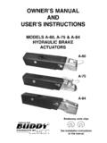
2 Brake towing vehicle hard and brakes on trailer are applied cylinder push rod spring assembly protects system from hydraulic 3 SAFETY SIGN LOCATIONST ypes of safety sign and locations on equipment are shown in illustration below. Good safetyrequires that you familiarize yourself with various safety signs, type of warning, and area orparticular function related to that area, that requires your SAFETY decal positioned as shownPart # BH21003 Page 4 BOLT TORQUE TORQUE DATA FOR STANDARD NUTS, BOLTS, AND all bolts to torques specified in chart unless otherwise noted. Check tightness of boltsperiodically, using bolt chart as guide. Replace hardware with same grade : Unless otherwise specified, high-strength Grade 5 hex bolts are used throughout assemblyof Torque for Standard bolts *GRADE 2 GRADE 5 GRADE 8 A lb-ft( )lb-ft( )lb-ft( )1/4 6(8)9(12)12(16)5/16 10(13)18(25)25(35)3/8 20(27)30(40)45(60)7/16 30(40)50(70)80(110)1/2 45(60)75(100)115(155)9/16 70(95)115(155)165(220)5/8 95(130)150(200)225(300)3/4 165(225)290(390)400(540)7/8 170(230)420(570)650(880)1 225(300)630(850)970(1310)Torque figures indicated are valid fornon-greased or non-oiled threads andheads unless otherwise , do not grease or oil bolts orcapscrews unless otherwise specifiedin this manual.
3 When using lockingelements, increase torque valuesby 5%.* GRADE or CLASS value for boltsand capscrews are identified by theirhead SpecificationsCLASS A lb-ft( )lb-ft( )lb-ft( )69(13)10(14)13(17)715(21)18(24)21(29)82 3(31)25(34)31(42)1045(61)50(68)61(83)127 8(106)88(118)106(144)14125(169)140(189)1 70(230)16194(263)216(293)263(357)18268(3 63)----364(493)20378(513)----515(689)225 16(699)----702(952)24654(886)----890(120 6)Bolt Torque for Metric bolts *GRADE-2 GRADE-5 5 The weight rating of the coupler is dependent on thecorrect bolts being used. You must use the boltsprovided with the product. If you are missing bolts,refer to your Operator s Manual and obtain replace-ments from Demco, or use the exact size, grade, andnumber of bolts as specified. Using the wrong size,grade, or number of bolts will reduce the weight rat-ing of the coupler and could cause separation of yourtowing equipment from the towing vehicle.
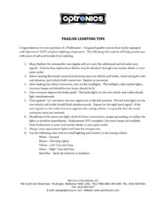
4 If youhave questions about the correct bolts for your ap-plication call Demco at any of the following telephonenumbers:(712) 725-2311(712) 725-23021-800-543-3626 FAX: 1-800-845-6420 WARNING: TO AVOID PERSONAL INJURY OR PROPERTYDAMAGE, OBSERVE THE FOLLOWING INSTRUCTIONS:!WELDINGTack Actuator down on thefour corners then weld in acriss cross pattern using 2 to 2-1/2 welds with 2 spaces between welds(when welding down to aflat area of the tongue)Do not weld in thecircled areaDo not weld in thecircled areaKeep braces and weldsback to allow access toshock pin holesKeep bracesand weldsback to allowaccess toshock pin holeUse gussets to sup-port the back of theactuator if welding inposition shownKeep gussetson rear of ac-tuator to lowerhalf to avoidcircled areaWeld as shownNOTE: disassembly of the actuator before welding is recommendedPage 643164988557999**2223132110**111414**161 9181724201515 MODEL DA10 ACTUATOR PARTS Slider Tube Chan.
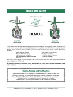
5 Down (Shown)-11053-??-Inner Slider Tube Channel Center-11063-??-Inner Slider Tube Channel Wear Wear Shock Pin (zinc plated) Case (11068 shown see page 15 for others) Pin (zinc plated) " x 1-1/4" Cotter Shock Pin (zinc plated)** Lever Spring (zinc plated) " External Tooth Lock "-18 UNC x 5/8" Hex Head Bolt "-20 UNC x 2" Hex Head Bolt " Lock Washer** Lever (zinc plated) Rod Master Cylinder (drum brakes)-111901 Composite Master Cylinder (disc brakes)19. 09153-Replacement Master Cyl. Gasket " pipe - 3/16" Fitting w/ Orifice (drum)-0567911/8" pipe - 3/16" Inverted Flare Fitting (disc) Cylinder Cap w/ Diaphragm and O-Ring-05849-O-Ring (replacement)** " Cable with hooks (both ends)-SB10555-Replacement S-hooks Guide (zinc plated)-BH21003-Replacement Towable/Not Towable Cyl. Protective -20 UNC Hex DA10 ACTUATOR PARTS #5404 PARTS Black Cylinder Gasket (not shown) Fitting Str.
6 2 HB x 10-32 Nipple 1/8 MPT x 1/8 Elbow 1/8 MPT x .2 HBDrill the hole using a 5/32 bit. Hole locationis .900 right of top left corner and .900 downfrom top of master cylinder. Tap hole with 10-32 NF tap26272930313230 Note: -?? = -95 Plated-97 Primed RedIndicate color when ordering partsPlease order replacement parts by PART NO. and DESCRIPTIONR emove Fitting (#20)from Master Cylinderand relocate to this hole5398 Master CylinderRepair Kit (drum)(gasket 09153 included)5482 Master CylinderRepair Kit (disc)(gasket 09153 included)-5401-Lever Replacement Kit (incl. items w/**)Outer Case WithoutMounts and ChannelDown Slider TubeShown, See Page 15for Other Options(OPTIONAL) FREE BACKINGSOLENOID KIT PARTS BREAKDOWN5404 (FIELD INSTALL) 5629 (FACTORY INSTALL)5650 Master Kit(drum)(gasket 09153 andfasteners included)5672 Master Kit(disc)(gasket 09153 andfasteners included)Page 7 OUTER CASE OPTIONS AND AVAILABLE HITCH Case w/ no mounts (primed red) Case w/ 6 hole Case w/ 50 mount (primed red) Case w/ universal Case w/ channel mount (primed red) Case w/ angle mounts (primed red) ,000 lb.
7 " Lever Lock Coupler Slider Tube (drop) Ring (6 Ton Capacity) "-11 UNC x 4 1/2" Hex Head Bolt "-11 UNC Stover Lock "-11 UNC Nylon Insert Lock " Bulldog Coupler Welded to Clevis Channel-05557-??12-5/16" Bulldog Coupler Welded to Clevis " Lever Lock Coupler Slider Tube (straight) Slide Tube w/ Flat "-11 UNC x 1-1/2" Hex Head Bolt " Lever Lock Channel Down Inner Slider Tube4444424848434347462 5/6 RATED AT 12500#492 5/16 RATED AT 12500#50484845484843432 5/16 RATED AT 12500#4241 RATED AT 12500#48483948 RATED AT 12500#48432 RATED AT 7000#333435383736 Please order replacement parts byPART NO. and DESCRIPTION : -?? = -95 Plated-97 Primed Red Indicate color when ordering partsThe weight rating of the coupler is dependent onthe correct bolts being used. You must use the boltsprovided with the product.
8 If you are missing bolts,refer to your Operator s Manual and obtain replace-ments from Demco, or use the exact size, grade, andnumber of bolts as specified. Using the wrong size,grade, or number of bolts will reduce the weight rat-ing of the coupler and could cause separation ofyour towing equipment from the towing vehicle. Ifyou have questions about the correct bolts for yourapplication call Demco at any of the following tele-phone numbers:(712) 725-2311(712) 725-23021-800-543-3626 FAX: 1-800-845-6420 WARNING: TO AVOID PERSONAL INJURY ORPROPERTY DAMAGE, OBSERVE THE FOLLOW-ING INSTRUCTIONS:!2 5/16 RATED AT 12500#404848 Page 8 DEMCO MODEL DA10 BRAKE ACTUATORINSTALLATIONM odel DA10 is completely assembled and ready to bolt or weld into actuators come with a variety of mounting channels. (see Page 15) and tighten all brake master cylinder (#18) with DOT 3 or 4 brake brake system using a pressure-type brake bleeder or manually, as two 5/16" hex head bolts (#13) and lock washers (#12) that hold lever guide(#23) and flat emergency lever spring (#11).
9 Remove lever guide and emergency lever short strokes, pull forward on emergency lever (#16), pumping master cylinder untilbrake fluid within master cylinder stops a bleeder hose to bleeder valve on one of the wheels and submerge other end of hoseinto a transparent container partially filled with brake fluid. Loosen bleeder valve one turnand, watching hose in transparent container, use emergency leverto pump master cylinderas long as air bubbles continue to leave the hose. When bubbles stop, close bleeder valve,move to next wheel, and repeat process until all brakes have been bled. (Note: Check fluid levelin master cylinder frequently while bleeding brakes (every 4 or 5 strokes). Refill as necessaryto keep level above half full.) Review all of the following instructions before installation and use of hydraulic brake actuator.
10 Dealers or Distributors must review these instructions with ultimate user. Failure to follow these instructions, or failure to properly maintain braking system afterinstallation, can result in loss of braking action which could cause severe property damage,personal injury or Prevent Serious Injury Or Death:WARNINGWARNINGM odel DA10 brake actuator has a maximum load rating of 12,500 and 1,000 lbs. tongue avoid personal injury or death, do not exceed lowest of (1) the ratedcapacity of Model DA10 actuator, or (2) rated capacity of ball, hitch, andcoupler being used, or (3) trailer's Gross Vehicle Weight Rating (GVWR).Model DA10 brake actuator has a maximum tongue load equal to 10%of the maximum load check brake fluid level. (Fluid must be approved, clean and uncontaminated.) sure actuator mounting bolts are actuator, replace bent, worn or damaged constantly aware of systems braking quality, make periodic checks as described in brakes ownersmanual.