Transcription of Door Frame Installation Instructions - Fleetwood Aluminum
1 Door Frame Installation Instructions For Nail-fin and Block Frames DOC NO: Door Installation Instructions REV: O DATE: 6/29/2017 Page 1 of 5 General The key to any window or door Installation is preparation. This extends from storage of the product to the final Installation and to all points in between. Careful planning and attention to detail can help ensure proper Installation . Operational Warning 1. Fleetwood products operate smoothly and special care should be taken by the owner to make sure users are not injured. 2. Live or dead loads transferred into our product can affect functionality, damage Frame joinery or cause glass failures. Dead loads such as upper levels, roof, etc. should be constructed before Door or Window is installed. 3. Loads shall be designed to withstand the most critical effects of load factors and load combinations as required by the building code.
2 (Loads are including but not limited to Live, Dead, Collateral, Auxiliary, Thermally induced, Seismic, etc.) 4. Maximum vertical deflection of the header under all Load combination should not exceed the Span/720 or whichever is less. Note: For installations beyond these limitations, a structural engineer should be consulted for specific requirements. Storage doors are finished products and must be protected against damage. When storing doors , handle the materials carefully. To avoid racking or damage to the products or their accessories, do not drop or drag them from the delivery truck. Add adequate non-abrasive pads between panels as separators so the products do not rub together. Be sure to store the doors off the ground ( , on pallets or planks, etc.). Protect the stored products against the elements by using a well ventilated covering, preferably inside in a dry environment.
3 If the packaging becomes wet, unpack the doors and repack with dry materials, then move to a dry location. Wet cardboard can cause swift and severe damage to anodized and painted finishes. Sealant Requirements 1. The sealant referred to within this document for seals associated with the assembly of the product should conform to AAMA 800-92. It is recommended that all other sealants should also conform to AAMA 800-92 but may be a sealant recommended and approved by the sealant manufacturer that is compatible with the door framing, finish and surrounding materials. 2. The size of all sealant beads must not exceed minimum or maximum sizes recommended by the sealant manufacturers. 3. Some exterior wall finishes require additional sealing between the perimeter of the door Frame and adjacent finish wall material. The Owner / General Contractor is responsible for identifying the need for any additional sealant which will be applied by others.
4 Such sealant shall be elastomeric material, with the door framing, finish and surrounding materials. Sillpan Substitution If the factory provided sillpan is not desired, the product warranty will remain intact if the substitute panning system emulates the essential design of the factory pan. Some sliding door systems have passed specific air, water, energy and structural testing with the factory provided sillpan. Extreme Weather Conditions (Thermally Broken Product Only) 1. For installations that will be exposed to extreme weather, apply a compatible sealant on top of the thermal break cavity of all sills, t-bars and stack bars. 2. A sillpan is provided to ensure that any water that penetrates the thermal break, mulled connection or water weeped through the sill is collected and directed to the exterior of the building.
5 In extreme cold weather Door Frame Installation Instructions For Nail-fin and Block Frames DOC NO: Door Installation Instructions REV: O DATE: 6/29/2017 Page 2 of 5 conditions Fleetwood recommends that metal sillpans be replaced or covered with a nonconductive material to avoid frost or condensation from migrating to the interior of the building. Assembly and Installation It is essential that each Fleetwood product be assembled and glazed in accordance with AAMA standards and factory Instructions . Please refer to the specific product assembly and glazing Instructions on separate sheets. If necessary, contact the factory to obtain a copy of these Instructions . It is the installer s responsibility to ensure that each Fleetwood product is assembled, glazed and installed and completely sealed to ensure that the product is leak-free and operates correctly.
6 Installation of Fleetwood products must be in accordance with the standards set forth in ASTM E 2112. If there are any questions regarding the Installation of a Fleetwood product contact the factory customer service department. Nail-fin Door Frames The following procedure applies to all Nail-fin installations. Note: The flashing referred to in this document is Moistop paper flashing but may refer to other code compliant flashing material that conforms to Federal Specification UU-B-790a, Type 1, Grade A, Style 4. When using Moistop paper, the strips of paper are to be no less than 9 inches wide (or wider as required by local codes). Flashing paper must be applied with galvanized nails or corrosion resistant staples. Flashing paper shall be applied in a weatherboard fashion around the full perimeter of the framed opening.
7 1. Check the measurements of the opening and make sure that the door Frame you have will fit the opening. 2. Remove the Frame from the packaging and lay it in front of the opening. (NOTE: DO NOT ASSEMBLE YET, applies to Aluminum product only.) 3. Place the sill of the door Frame on the masonry sill and use it as a straight edge (protect the finish from damage). Place a level on top of the Frame sill to determine if the masonry is level and if there are any crowns or dips. 4. Place the non-porous, non-absorbent, inorganic shims on the floor to build up low areas to level. Seal under the shims placed in the low spots in the masonry sill. NOTE: unless the Frame sill is perfectly level the sliding panel will not line up in both the closed and completely open position. 5. Plumb the trimmer on the lock side and nail into place.
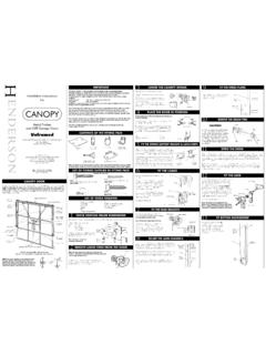
8 APPLY SEALANTTO THE BACK SIDEOF L-SHAPED CORNER6. Prepare the opening to accept the door Frame ensuring that the weep-screed or flashing at the sill is adjusted to maintain a weatherboard style flashing. 7. Apply a PVC liner or water proof material to ensure separation of the metal Frame with the substrate. 8. In balcony situations flash the sill with Aluminum break metal. Figure 1a Door Frame Installation Instructions For Nail-fin and Block Frames DOC NO: Door Installation Instructions REV: O DATE: 6/29/2017 Page 3 of 5 9. Assemble the Frame . Apply sealant to the back side of the L-shaped Aluminum corner pieces (if required) and attach to the exterior face of the nail-fin at the corners of the head as shown in figure 1a. Seal the joints completely with compatible sealant.
9 IMPORTANT: Apply a heavy bead of sealant to the interior side of the mounting flange (nail-on) where the door Frame jamb and sill join. Sealant must cover the entire joint (from the flange to the inside leg of the door) and extend 1-1/2 up the jamb and along the sill. (See figure 1b). Figure 1b 10. Apply compatible sealant to the underside of the Frame sill. Apply the sealant as far to the outside of the opening as possible. 11. Immediately prior to installing the Frame , apply a continuous 1/2" bead of compatible sealant to the backside (interior) of the mounting flange (nail-fin) at the jambs and head. Insert the door Frame into the opening and set the sill in a full bed of sealant and tight with the lock jamb side trimmer. (See fig. 2) 12. Secure the jamb to the trimmer. ( #8 x 2" stainless steel counter sink head).
10 Seal all fastener heads during Installation with sealant. Figure 2 13. Pull the trimmer on the fixed side tight with the jamb. Cross measure and adjust the Frame as necessary to achieve a plumb square and level condition. Secure the fixed jamb to the trimmer with screws (#8 x 2" stainless steel counter sink head). Seal all fastener heads during Installation with sealant. 14. Nail the trimmer on the fixed side into place and block both trimmers. 15. The installer is responsible for the integrity of all framing and pan joints after Installation and must therefore water test all joints to guarantee a completely sealed product. Apply joint sealer and/or sealant necessary to ensure watertight joints. Retest as necessary. 16. Once satisfied that the door Frame and pan is water tight, and immediately prior to application of the flashing paper at the head and jambs, apply a continuous bead of sealant to the exposed mounting flange (nail-fin) at the top (head) and sides (jambs) of the installed door.