Transcription of Doppler Ultrasound - Principles and practice
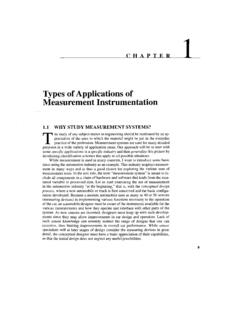
1 Doppler in Obstetrics: book by K Nicolaides, G Rizzo, K Hecher Chapter on Doppler Ultrasound : Principles and practice by Colin Deane INTRODUCTION Competent use of Doppler Ultrasound techniques requires an understanding of three key components: The capabilities and limitations of Doppler Ultrasound ; The different parameters which contribute to the flow display; Blood flow in arteries and veins. This chapter describes how these components contribute to the quality of Doppler Ultrasound images. Guidelines are given on how to obtain good images in all flow imaging modes. BASIC Principles Ultrasound images of flow, whether color flow or spectral Doppler , are essentially obtained from measurements of movement.
2 In Ultrasound scanners, a series of pulses is transmitted to detect movement of blood. Echoes from stationary tissue are the same from pulse to pulse. Echoes from moving scatterers exhibit slight differences in the time for the signal to be returned to the receiver (Figure 1). These differences can be measured as a direct time difference or, more usually, in terms of a phase shift from which the ` Doppler frequency' is obtained (Figure 2). They are then processed to produce either a color flow display or a Doppler sonogram. As can be seen from Figures 1 and 2, there has to be motion in the direction of the beam; if the flow is perpendicular to the beam, there is no relative motion from pulse to pulse.
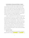
3 The size of the Doppler signal is dependent on: Blood velocity: as velocity increases, so does the Doppler frequency; Ultrasound frequency: higher Ultrasound frequencies give increased Doppler frequency. As in B-mode, lower Ultrasound frequencies have better penetration. The choice of frequency is a compromise between better sensitivity to flow or better penetration; The angle of insonation: the Doppler frequency increases as the Doppler Ultrasound beam becomes more aligned to the flow direction (the angle between the beam and the direction of flow becomes smaller). This is of the utmost importance in the use of Doppler Ultrasound .
4 The implications are illustrated schematically in Figure 3. Figure 1: Ultrasound velocity measurement . The diagram shows a scatterer S moving at velocity V with a beam/flow angle. The velocity can be calculated by the difference in transmit-to-receive time from the first pulse to the second (t2), as the scatterer moves through the beam. Figure 2: Doppler Ultrasound . Doppler Ultrasound measures the movement of the scatterers through the beam as a phase change in the received signal. The resulting Doppler frequency can be used to measure velocity if the beam/flow angle is known. Figure 3: Effect of the Doppler angle in the sonogram.
5 (A) higher-frequency Doppler signal is obtained if the beam is aligned more to the direction of flow. In the diagram, beam (A) is more aligned than (B) and produces higher-frequency Doppler signals. The beam/flow angle at (C) is almost 90 and there is a very poor Doppler signal. The flow at (D) is away from the beam and there is a negative signal. All types of Doppler Ultrasound equipment employ filters to cut out the high amplitude, low-frequency Doppler signals resulting from tissue movement, for instance due to vessel wall motion. Filter frequency can usually be altered by the user, for example, to exclude frequencies below 50, 100 or 200 Hz.
6 This filter frequency limits the minimum flow velocities that can be measured. CONTINUOUS WAVE AND PULSED WAVE As the name suggests, continuous wave systems use continuous transmission and reception of Ultrasound (Figure 4). Doppler signals are obtained from all vessels in the path of the Ultrasound beam (until the Ultrasound beam becomes sufficiently attenuated due to depth). Continuous wave Doppler Ultrasound is unable to determine the specific location of velocities within the beam and cannot be used to produce color flow images. Relatively inexpensive Doppler Ultrasound systems are available which employ continuous wave probes to give Doppler output without the addition of B-mode images.
7 Continuous wave Doppler is also used in adult cardiac scanners to investigate the high velocities in the aorta. Doppler Ultrasound in general and obstetric Ultrasound scanners uses pulsed wave Ultrasound (Figure 4). This allows measurement of the depth (or range) of the flow site. Additionally, the size of the sample volume (or range gate) can be changed. Pulsed wave Ultrasound is used to provide data for Doppler sonograms and color flow images. Figure 4: Illustration of continuous wave and pulsed wave Doppler . Aliasing Pulsed wave systems suffer from a fundamental limitation.
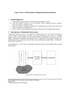
8 When pulses are transmitted at a given sampling frequency (known as the pulse repetition frequency), the maximum Doppler frequency d that can be measured unambiguously is half the pulse repetition frequency. If the blood velocity and beam/flow angle being measured combine to give a d value greater than half of the pulse repetition frequency, ambiguity in the Doppler signal occurs. This ambiguity is known as aliasing (Figures 5 and 6). A similar effect is seen in films where wagon wheels can appear to be going backwards due to the low frame rate of the film causing misinterpretation of the movement of the wheel spokes. Figure 5: Aliasing of color Doppler imaging and artefacts of color (left).
9 Color image shows regions of aliased flow (yellow arrows). This problem is avoided by reducing color gain and increasing pulse repetition frequency (Right). Figure 6: Example of aliasing and correction of the aliasing. Left: waveforms with aliasing, with abrupt termination of the peak systolic and display this peaks bellow the baseline. Right: Sonogram clear without aliasing. Correction: increase the pulse repetition frequency and adjust baseline (move down) The pulse repetition frequency is itself constrained by the range of the sample volume. The time interval between sampling pulses must be sufficient for a pulse to make the return journey from the transducer to the reflector and back.
10 If a second pulse is sent before the first is received, the receiver cannot discriminate between the reflected signal from both pulses and ambiguity in the range of the sample volume ensues. As the depth of investigation increases, the journey time of the pulse to and from the reflector is increased, reducing the pulse repetition frequency for unambiguous ranging. The result is that the maximum d measurable decreases with depth. Low pulse repetition frequencies are employed to examine low velocities ( venous flow). The longer interval between pulses allows the scanner a better chance of identifying slow flow. Aliasing will occur if low pulse repetition frequencies or velocity scales are used and high velocities are encountered (Figure 7).