Transcription of Dosing Pots - Water Treatment Products
1 Publication WTP/Pot/12/06 Dosing Pots Dosing pots are required in order to feed liquid chemicals such as corrosion inhibitors into closed systems. The units consist of a mild steel vessel with inlet (return) and outlet (flow) valves drain valve filling valve steel tundish air release valve wall mounting brackets non-return valve. Dosing pots are handed (left or right) for ease of installation. Specification Mild steel shell to BS 1387 (up to 150mm, schedule 20 used on 200mm and above) Welded to BS EN 287 All Dosing pots that are designed to PD 5500:2000 category 3 (C E marked) Maximum Working pressures.
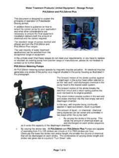
2 O 14 litres to 6 litres inclusive o 10 bar- 10 litre to 20 litres inclusive o 8 bar-25 litres Dosing pots that are not designed to the above are available which have a maximum working pressure of 14 bar throughout the range ( litre to 25 litre) Powder coated paint finish Overall Dimensions (mm) Pressures (bar) Size (litres) Height Width Connection Valves (mm) WorkingTest 540 265 15 14 21 720 315 15 10 15 775 375 25 8 12 CDBANon Return ValveDrainSystem FlowSystemReturnAir CockTundishDiagram 1 CDBANon Return ValveDrainAir CockTundishDiagram 2 InstallationThe units should be wall mounted via the integral brackets at a height such that it is convenient and safe to pour chemicals into the should also be given to the drain from the dosage drain valve can be piped to a
3 Permanent foul drain. Alternatively there should be sufficient space beneath the drain valve to place a suitable vessel capable of taking the volume of liquid in the dosage pot. Any liquid drained from the pot should subsequently be disposed of via a foul should be made to the system to be treated such that there is sufficient pressure differential across the dosage pot to ensure that there is adequate flow throughout the 1 illustrates a typical closed circuit to the Dosage Pot should be to the system flow and choosing a suitable point for the connections, consideration should be given to the fact that a pressure differential is necessary to effect flow through the Dosage 2 illustrates a connection across a recirculating or feed this installation method can be used for cooling tower biocide dosage.
4 Shot Dosing of steam boilers or as an alternative to the above method of Dosing closed either application, care must be given to ensure that the pressure generated by the system being treated does not exceed the pressure rating of the Dosage Pot. Operating Instructions Chemicals Prepare the chemicals to be dosed. Refer to relevant Safety Information Sheet which should be displayed at the point of use. To Drain 1. Ensure Water in Dosage Pot is not dangerously hot. 2. Close all valves. 3. Open Drain Valve D and allow air to enter the Dosage Pot by opening the Air Cock valve. Ensure the unit drains completely. To Fill 1. Close the drain valve D, leaving the Air Cock valve open, and open the fill valve A.
5 2. Slowly pour the chemicals into the Dosage Pot via the Tundish. 3. When liquid appears at the outlet from the Air Cock valve, cease filling and close the Air Cock valve. 4. Close the fill valve A. Chemical Injection 1. Open valves B & C to allow system Water to flow through the Dosage Pot and inject chemical into the system. Allow at least 10 minutes circulation for complete injection. 2. The procedure should be repeated until the desired level of chemical in the system is achieved and then concluded with clean Water to ensure correct operation of all valves. 3. After use the Dosage Pot can be left in circulation, or isolated, full or empty. Maintenance After long-term use the valves may require replacement.
6 The Dosing pot should be checked annually to check for any corrosion wear. 1mm corrosion allowance is provided for in the design. If corrosion is found to be greater than 1mm the Dosing pot should be taken out of use.