Transcription of DOUBLE PILOT OPERATED LOCK VALVES METRO …
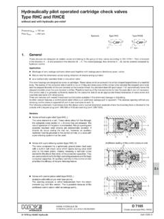
1 9 D-601 DOUBLE PILOT OPERATED LOCK VALVES Flow Capacity Pressure Rating Temperature Range Weight See Performance Graph 2500 PSI -22 to + 194 F -30 to + 90 C 3 lbs 4 oz ( kg) SPECIFICATIONS The D-601 Lock Valve is designed to lock a cylinder or part of a circuit while a directional control valve is in the neutral position, specifically for applications where directional control valve leakage could adversely affect the performance of the system. In addition, this lock valve also has built in integral relief's for thermal or ex-cess pressure shocks on the locked part of a circuit.
2 With the directional control valve in the neutral position, flow from both ends of a cylinder is locked by the D-601 Lock Valve. When the directional control valve is activated, flow is directed to one side of the valve unseating the ball check on that side. This al-lows PILOT pressure to open the poppet on the opposite side of the valve and allow flow to return to tank. The PILOT pressure required to unlock the load is approximately 20% of the difference between the internal relief setting and the load induced pressure.
3 1. Prevents load from dropping faster than fluid is supplied to the actuator by the pump. 2. locks actuator in selected position when no motion is de-sired. 3. Relieves excess pressure on system caused by load or ther-mal expansion. 4. Provides an emergency manual release for lowering load in case of power failure. 5. Requires less power when load is being raised or lowered. 6. Permits smooth movement and eliminates actuator chatter or cavitations. 7. Prevents load drifting due to directional valve leakage.
4 APPLICATION A PILOT OPERATED check valve (lock valve) should be incorpo-rated in every loader, outrigger, back-hoe, work platforms. ORDERING INSTRUCTIONS D-601 08 Model Number Port Size D-601 08 - 3/4 16 #8 SAE GPM L/MIN 15 (56) 6 (22) 9 (34) 12 (45) 3 (11) ( ) 500 ( ) 600 ( ) 400 ( ) 300 (0) 0 ( ) 200 ( 100 (BAR))
5 PRESSURE DROP CHARACTERISTICS 1. Valve Port to Cylinder Port 2. Cylinder Port to Valve Port METRO MACHINE & ENGINEERING 952-259-3623 10 407, 408, 409 DOUBLE LOCK VALVE 411, 412 SINGLE LOCK VALVE OPERATION With the directional control valve in the neutral position, flow from both ends of a cylinder is blocked, locking the cylinder piston in position by the DOUBLE Lock Valve. When the directional control valve is shifted to direct flow to one side of the cylinder, pressure opens the check ball and simultaneously moves the piston over to the opposite side of the valve opening this check ball allowing free flow return to the directional control valve.
6 The 407 lock valve has two adjustable flow controls, and the 408 has one adjustable flow control which, by adjusting in or out, changes the pressure drop in the VALVES . This in most cases, smoothes our pulsations and eliminates valve chatter. Single Lock VALVES are also available. The 411 single lock is non-adjustable and the 412 single lock is adjustable. APPLICATION Typical applications are loaders, outriggers, back hoes, cranes, fork lifts, work platforms, hydraulic winches, land planes, wing lifts, gauge wheels or any application where loads must be held in neutral position.
7 A 4-way control valve is required for all lock valve circuits, in-cluding single-acting cylinders, in order to apply unlocking pressure to the PILOT circuit. The position PILOT ratio is 3:1. The amount of pressure required in the PILOT circuit of the valve to unlock a single-acting cylinder is 30% of the locked pres-sure. The amount of pressure required in the PILOT circuit of the valve to unlock a single-acting cylinder is a function of cylinder ar-eas and trapped pressure. When the base end of the cylinder is locked use this formula for calculating the unlocking pressure.
8 Pressure on the rod end Unlocking pressure = 3 - Cylinder area - Rod area Cylinder area When the rod end of the cylinder is locked use this formula. Pressure on the base end Unlocking pressure = 3 - Cylinder area CAUTION: Note that when the rod end of a DOUBLE -acting cylinder is locked, if the rod diameter exceeds approxi-mately .75 times the cylinder diameter, unlocking pressure becomes excessive. Model Number Port Size 407 DOUBLE 408 DOUBLE 409 DOUBLE 411 Single 412 Single 02= 1/4 -18 NPT 03= 3/8 -18 NPT 04= 1/2 -14 NPT 05= 3/4 -14 NPT 06= 9/16 -18 #6 SAE 08= 3/4 -16 #8 SAE 10= 7/8 -14 #10 SAE SPECIFICATIONS Flow Capacity Pressure Rating Temperature Range Weight See Performance Graph 3000 PSI (207 Bar) -22 to + 194 F -30 to + 90 C 407 2 lbs.
9 8 oz. ( kg.) 408 2 lbs. 6 oz. ( kg.) 409 2 lbs. 4 oz. ( kg.) 411 2 lbs. 1 oz. ( kg.) 412 2 lbs. 3 oz. ( kg.) ORDERING INSTRUCTIONS DESCRIPTION The DOUBLE Lock VALVES are designed to lock a cylinder or part of a circuit while a directional control valve is in the neutral position. Designed for applications where directional control valve leakage could adversely affect the performance of the system. 409 408 GPM L/MIN 4 (15) 8 (30) 12 (45) 16 (60) PRESSURE DROP CHARACTERISTICS 20 (75) (0) 0 (BAR) ( ) 200 ( ) 300 ( ) 400 ( ) 500 ( ) 100 1.
10 Valve Port to Cylinder Port 2. Cylinder Port to Valve Port METRO MACHINE & ENGINEERING 952-259-3623